
Manual

WI-I/O 9-x_WI-I/O-EX-1-S-x 2.16 Page 69
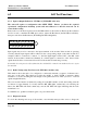
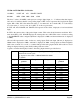
Transmitted messages are displayed starting in the leftmost column of the display. Received messages
are displayed with the received signal strength preceding the message. The first four hexadecimal digits
are the system address attached to the message, and must match for units to communicate successfully.
The received signal strength is in negative dBm - the lower the measurement, the stronger the radio
signal. A measurement larger than 95 indicates a weak radio signal.
Example:
>c
Comms
TX: 01FA8106008005C6727D44 Command message transmitted by this unit.
84 01FA8186C6E0E3 Acknowledge received from remote.
81 01FA860100800100009286 Message received from remote unit.
TX: 01FA868100FCE4 Acknowledge message from this unit to remote.
<INVALID> 01FA860000800100009286 Corrupted message received.
DO1 to DO8, DIO1 to DIO12
These options allow the user to set and clear digital outputs. To set an output, select the corresponding
menu item, at the prompt, type the value FFFF to turn the output ON, or 0000 to turn the output OFF.
For example, to set DO1 ON,
>e
DO1
>FFFF
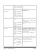
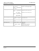
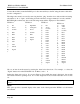
AO1 to AO8
These options allow the user to set analog outputs to any value. To set the output, select the
corresponding menu item. At the prompt type the value required for the analog output as a four digit
hexadecimal value. Refer to the table above for analog current/expected value relationship. To set AO2
on WI-I/O-EX-1-13 to 19 mA :
>m
AO2
>B800
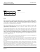
Switch
This option allows testing of the DIL (Dual In Line) switches. The diagram below indicates the layout
of the switches of which there are two sets of eight, with an “Enter” button located to the right of the
pair. the display indicates the current switch settings with the digit ‘1’ corresponding to ‘On’ and the
digit ‘O’ corresponding to ‘Off’. Changing the switch settings in this mode will change the display.
Test each switch and check to ensure the display changes accordingly.