
Manual


WI-I/O 9-x_WI-I/O-EX-1-S-x 2.16 Page 73
6.3 Radio Path Testing
To carry out a radio path test, you will need two WI-I/O 9-x modules. One module will be “fixed” and
the other “mobile”. Both units will need power supplies and antennas. The power supply for the
mobile unit is normally a 12V battery, but make sure that the battery is fully charged - batteries with
low voltage will lead to low radio power which will affect the test result.
The object of the test is to determine whether radio paths are reliable, marginal or unreliable. A
reliable path will have a margin of at least 10dB above the background noise level in good weather -
this margin is enough to ensure that the radio path remains reliable in poor conditions. A marginal path
will work reliably in good conditions, however will fail during poor conditions. If the test is carried
out during rainy or foggy weather, then a margin of only 5dB is required.
Procedure:
Configure the modules to the same system address, and on each module, configure DI1 to DO1 on
the other module. At the fixed module, wire DO1 to DI1 such that DI1 will turn ON when DO1
turns ON. Connect a switch to DI1 on the mobile unit.
When the modules are close to each other, test the system - close the switch, forcing the mobile
unit to transmit. The mobile unit will transmit to the fixed unit, and the fixed unit will transmit
back to the mobile unit, activating DO1. Turning off the switch will result in two radio
transmissions, turning off DO1. Each time the switch is changed, there should be two radio
messages (two sets of TX/RX flashes) at the mobile unit. Note that when the modules are within a
couple of metres, they may not work well with antennas connected - in this case, test without
antennas.
Set up the fixed module in one of the test positions - this is normally at a control centre or repeater
site. Fix the antenna in a temporary fashion. You will need to make an initial assessment on how
high the antenna should be mounted.
Take the mobile module to the other end of the radio path. The antenna at this end can be either
held by the tester, or fixed in a temporary fashion. Note that a person’s body will affect the
radiation pattern of an antenna, so if the antenna is hand-held and the test is not successful, try
again with the antenna fixed to a 1 metre length of plastic pipe or timber. The tester holds the
length of pipe or timber with the antenna above head height.
Test the radio path by operating the switch. If the radio path is short, and there is a high level of
confidence that the radio path will be reliable, the result can be checked by simply looking at the
TX/RX leds on the mobile unit. If each TX flash is followed immediately by a RX flash (that is,
the TX flash does not flash twice or more times before the RX flashes), then the radio path is
likely to be reliable. Operate the switch several times - do not rely on one test. If the test is being
done outside, the leds will need to be shaded to view the flashes.
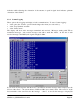
If the radio path is uncertain, then the result should be measured by connecting a laptop computer,
following the procedure outlined in this manual for measuring the radio signal strength. Before the
switch is operated, the background noise level should be measured and recorded. This