
Manual


WI-I/O 9-x Wireless Module User Manual v2.16
WI-I/O-EX-1-S-x Serial Module
Page 80
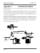
Note the following points in the configuration:
• Note that no repeater address is necessary
between #1 and #94.
• DIN2 (pump running signal) has two mappings
- a mapping to DO1 at #2 (tank station) and
DO2 at #94 (control station). When DIN2
changes, there will be two separate change
messages transmitted - one by radio to #2 and
one by serial link to #96.
• AIN1 (pump amps) is mapped to AO3 at #94
(control station).
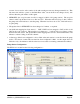
• An additional mapping has been entered - LOW VOLT has been mapped to DO8 at the control
station. This mapping is for future use - it will provide a low battery voltage alarm for the pump
station.
• A Start-up poll has been configured for #2, as DO2 at the pump station is controlled from the tank
station. Note that a comms fail reset time of 11 minutes has been configured for DO2. This means
that if a message has not been received for DO2 within 11 minutes, DO2 will reset and switch off
the pump. The 11 min time was chosen as it means that two successive update messages have to be
missed before the pump is reset, and there is no problems if the pump runs for 11 minutes during a
system failure (the tank will not overflow during this time).
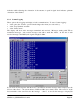
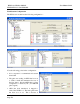
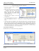
Control Station Configuration
The WI-I/O-EX-1-S-3 module has the following configuration :-
Note the following points in the configuration: