
Manual


WI-I/O 9-x_WI-I/O-EX-1-S-x 2.16 Page 81
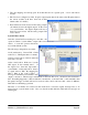
• The only mappings are Start-up polls. Note that there are two separate polls, one for each remote
module.
• PO 3 has been configured as a PO. Its pulse output update time is the same as the PI update time at
the remote module (both have been left at their
default value of 1 minute).
• Reset times have been selected for the analog outputs
(21 minutes) but not the digital outputs. In the event
of a system failure, the digital outputs will stay at
their last correct status, but the analog outputs will
reset to 0 mA.
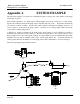
System Failure Alarm
After the system had been running for some time, the
operators wanted a "system failure" output at the control
station, to warn the operators that there
was a fault with the system.
The following configuration was added :
At #2 (tank station), Inverse DI4 → DO4
at #94 via 1 ; DI4 Update time = 1 minute
At #94 (control station), DO4 Comms fail
reset time = 3.5 min
At the control station, DO4 was a "system
OK" signal. It was normally active - if
the signal reset, then this represented a
system failure. At the tank station, there is
no signal wired to DI4. By mapping Inv
DI4 to DO4 at the control station, a
message is transmitted every minute to this
output to activate it. The message is transmitted via the radio link to #1, and then by the serial link to
#94. If anything happened to either module #2 or module #1, or the radio link, or the serial link, then
the update messages for DO4 will not be received at the control station module. After 3.5 Minutes,
DO4 will reset indicating a problem.
The time of 3.5 minutes was selected as this means that 3 successive update messages have to be
missed before a system alarm occurs. Also note, that if module #94 fails, DO4 will reset and give an
alarm signal.