User Manual WI-I/O-EX Serial I/O Module Weidmuller Inc., 821 Southlake Blvd., Richmond, VA 23236 Tel: (800) 849-9343 Fax: (804) 897-4136 Email: support@weidmuller.com Web: www.weidmuller.
WI-I/O-EX Serial I/O Module User Manual v1.11 Thank you for your selection of the WI-I/O-EX Serial I/O Module. We trust it will give you many years of valuable service. ATTENTION! Incorrect termination of supply wires may cause internal damage and will void warranty. To ensure your WI-I/O-EX product enjoys a long life, double check ALL your connections with the User Manual before turning the power on. All equipment must be properly grounded for safe operation.
WI-I/O-EX Serial I/O Module User Manual v1.11 CONTENTS 1 OVERVIEW ............................................................................................................... 4 1.1 MODULE TYPES AND FEATURES .........................................................................................5 1.1.1 Digital inputs / outputs................................................................................................6 1.1.2 Pulsed outputs.............................................................
WI-I/O-EX Serial I/O Module User Manual v1.11 APPENDIX E. RS232 WIRING .................................................................................... 55 1 Overview The WI-I/O-EX modules are designed to provide I/O expansion for other products like WI-I/O 9, WI-MOD-9-E and WI-MOD-E modules. The WI-I/O-EX modules support the WI Series protocol, and communicate serially via RS232 or RS485. Configuration is done via the WI Series configuration utility.
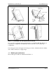
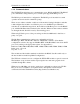
WI-I/O-EX Serial I/O Module User Manual v1.11 Status LEDs RS485 and power connector Address switches RS485 termination switch I/O connector RS232 configuration connector DIN rail mount Power OK Transmit Receive Analog configuration access panel Figure 1-1: WI-I/O-EX unit with significant parts labeled. Two ports allow configuration and communications on the WI-I/O-EX. The RS232 port is intended for configuration. The RS485 port allows the unit to be in a multi-drop configuration.
WI-I/O-EX Serial I/O Module User Manual v1.11 WI-I/O-EX -11 -12 -13 Digital inputs/outputs Up to 16 Up to 8 Up to 8 Pulse outputs 8 8 8 Pulse inputs 4 - - Analog inputs - 4 floating or 8 commoned - Analog outputs - - 8 Table 1-1: Summary of WI-I/O-EX module types and I/O. 1.1.1 Digital inputs / outputs Each digital I/O channel on the WI-I/O-EX modules can act as either an input or an output. The input/output direction does not need to be user configured.
WI-I/O-EX Serial I/O Module User Manual v1.11 to reach the Target within the update time. The output pulse rate is determined by the update time, and the difference between the count and the target. If the calculated pulse rate is more than the maximum rate (100Hz), the WI-I/O-EX will output pulses at the maximum rate. At the end of the update time, the count value will be less than the target.
WI-I/O-EX Serial I/O Module User Manual v1.11 The two types of input cannot be mixed - all inputs must be either “grounded” or “floating”. Inputs can also be selected as mA current, or voltage input - all inputs must be the same, either all current or all voltage.
WI-I/O-EX Serial I/O Module User Manual v1.11 1.1.6 Communications The WI-I/O-EX modules have two communication ports: RS232 and RS485. The RS485 port communicates using E-Series protocol. Both ports support ModBus protocol. The RS232 port is intended for configuration. The RS485 port is intended for normal operation and can be used in a multi-drop setup. There are two address switches on the base of the module.
WI-I/O-EX Serial I/O Module User Manual v1.11 2 Installation All connections to the module should be SELV only. Normal 110/220/240V mains supply should not be connected to any input terminal of the module. 2.1 General installation Several WI-I/O-EX modules may be connected to one master via RS485 multi-drop connection as shown in Figure 2-1. Ensure there is good grounding between the WI-I/OEX units and the master. A 2.5 mm2 / 12 gauge earth wire is recommended.
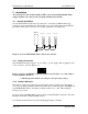
WI-I/O-EX Serial I/O Module User Manual v1.11 You can connect to an WI-GTWY-9-MD1 Module using either MODBUS protocol or ESeries protocol. E-Series protocol is easier to set up, and we recommend using this protocol for most applications. x10 x1 Figure 2-3: Address switches. The address shown is 01. Connect the RS485 B and A wires to the 4-way connector shown previously in Figure 2-2. An RS485 termination switch is provided.
WI-I/O-EX Serial I/O Module 2.2 User Manual v1.11 Signal Connections All connections to the module should be SELV only. Normal 110/220/240V mains supply should not be connected to any input terminal of the module. 2.2.1 Digital Inputs (and Pulsed Inputs) The WI-I/O-EX-1-S-11 supports 16 digital signals, and the WI-I/O-EX-1-S-12 and WII/O-EX-1-S-13 support 8 digital signals. Additionally, digital inputs DIO1-4 on the WII/O-EX-1-S-11 operate as pulse inputs.
WI-I/O-EX Serial I/O Module User Manual v1.11 2.2.2 Digital Outputs (and Pulsed Outputs) The WI-I/O-EX-1-S-11 supports up to 16 digital outputs, shared with the digital input function on the same terminals. The WI-I/O-EX-1-S-12 and WI-I/O-EX-1-S-13 both provide 8 digital output signals. These signals are marked DIO1-8, and DIO1-16 for the WI-I/O-EX-1-S-11. On all WI-I/O-EX modules, DIO1-8 can also operate as pulsed outputs. When active, digital outputs provide a transistor switch to EARTH.
WI-I/O-EX Serial I/O Module User Manual v1.11 2.2.3.1 Grounded Single-Ended mA Inputs Single-ended current inputs allow twice as many inputs as the differential mode. This mode is useful when the sensor loop can be grounded to the WI-I/O-EX module. Devices may also be powered by the 24V supplied by the WI-I/O-EX. Refer to Figure 2-7: Loop powered sensor - + WI-I/O-EX Module ALS +24V AIN1 AIN2 Externally powered sensor + - AGND V- Figure 2-7: Connection for single-ended current inputs.
WI-I/O-EX Serial I/O Module User Manual v1.11 2.2.3.2 Floating Differential Mode mA Inputs Differential mode current inputs should be used when measuring a current loop which cannot be connected to earth or ground. This allows the input to be connected anywhere in the current loop. Common mode voltage can be up to 27VDC. Up to four loops can be connected, to terminal pairs [AIN1-AIN2], [AIN3-AIN4], [AIN5-AIN6], [AIN7-AIN8] - the former terminal is positive and the latter negative.
WI-I/O-EX Serial I/O Module User Manual v1.11 2.2.3.3 Floating Differential Voltage Inputs Differential voltage inputs allow a voltage to be measured when it cannot be referenced to earth or ground. The diagram in Figure 2-9 shows how to connect differential voltage inputs. The module has a 27V common mode input range. WI-I/O-EX-1-S-12 Module ALS +24V + + - AIN1 AIN2 AIN3 AIN4 Sensors with voltage signals AGND V- Figure 2-9: Connection for differential voltage input mode.
WI-I/O-EX Serial I/O Module User Manual v1.11 2.2.3.4 Single-ended Voltage Input Single-ended voltage inputs allow twice as many inputs as differential mode. This mode is useful when one end of the input voltage can be connected to the ground of the WI-I/OEX module. Figure 2-10 shows connections for single-ended voltage input. WI-I/O-EX-1-S-12 Module ALS +24V Sensor with voltage signal AIN1 AIN2 + AGND V- Figure 2-10: Connection for single-ended voltage input.
WI-I/O-EX Serial I/O Module User Manual v1.11 2.2.4.1 Current Output Current output mode may be configured for current source or current sink. Figure 2-11 shows the connections for current source mode. Figure 2-12 shows the connections for current sink. WI-I/O-EX-1-S-13 Module ALS +24V AI AOT1 AOT2 + V- AGND COM PLC - Figure 2-11: Connection for current source output.
WI-I/O-EX Serial I/O Module User Manual v1.11 Note: - The hardware configuration needs to be changed for this type of output connection - To change the hardware configuration, refer to section 4.5 2.2.4.2 Voltage Output Voltage output mode produces a voltage referenced to the module’s AGND. Figure 2-13 shows the connection for voltage output configuration. WI-I/O-EX-1-S-13 Module PLC VOLTAGE INPUT ALS +24V AI AOT1 AOT2 + V- AGND COM - Figure 2-13: Connection for voltage output configuration.
WI-I/O-EX Serial I/O Module User Manual v1.11 3 Configuration Use the WI Series Configuration utility to configure the WI-I/O-EX module to communicate to WI-I/O 9, WI-MOD-9-E and WI-MOD-E modules. - If you want to communicate using ModBus, then simply set the address using the address switches on the bottom of the module. Refer to section 2.1.2 for details on setting the address switches - Ensure the Address switches are set to “00” for E-Series protocol mode. Refer to section 2.1.
WI-I/O-EX Serial I/O Module User Manual v1.11 Figure 3-1: Configuration of WI-I/O-EX modules using Configuration Utility. When you select “Add a new Serial Unit” you will need to select the unit type. Select the correct module type here. Figure 3-2: Select the unit type. WI-IO-EX Manual v1.
WI-I/O-EX Serial I/O Module User Manual v1.11 Finally, you will be prompted to select the module address. You can choose to allow the configuration software to select an unused address for you, or you can select the module address manually. - Serial Module address must be in the range 96 to 127. - Every serial module that is connected to the same radio module needs a separate address. - You can use the same address on two different serial modules if they are connected to different radio modules.
WI-I/O-EX Serial I/O Module User Manual v1.11 4 Hardware Configuration Hardware Set-up allows the WI-I/O-EX hardware function to be adjusted to suit the application. To configure the hardware settings, you need: - Access to the DIP switches under the Analog Configuration Panel (refer Figure 1-1: WI-I/O-EX unit with significant parts labeled.) - Configuration Software to run on your PC.
WI-I/O-EX Serial I/O Module • • • User Manual v1.11 Set the “Port” setting to match the computer com port you have connected to. Set the “Slave Address” to match the address switch setting of the WI-I/O-EX. If you are using address “00” for E-Series Protocol, set the Slave Address to 100. Set the communications parameters. The default communications parameters are: Baud rate: 9600 Parity: NONE Stop bits: 1 Click the button labeled Connect to WI-I/O-EX.
WI-I/O-EX Serial I/O Module User Manual v1.11 Note that you will need to change the connection settings on the “Connect” page, and reconnect to the WI-I/O-EX. 4.2.2 Pulsed outputs Choose the folder tab labeled Pulsed Outputs Setup, as shown in Figure 4-3. Figure 4-3: Pulsed outputs setup page for a WI-I/O-EX-11. The pulsed outputs are available on all models. Clicking the button Read from WI-I/O-EX will read the pulse out update times from the WI-I/O-EX and display them on the form.
WI-I/O-EX Serial I/O Module 4.3 User Manual v1.11 WI-I/O-EX-11 configuration 4.3.1 Pulsed Inputs Choose the Pulse Inputs Setup page, as shown in Figure 4-4. Figure 4-4: Pulse inputs setup. Only available on a WI-I/O-EX-11 module. Clicking the Read from WI-I/O-EX button reads the existing maximum pulse rate settings from the WI-I/O-EX and displays them on the form. If pulse rate is to be used, the maximum pulse input rate must be set.
WI-I/O-EX Serial I/O Module 4.4 User Manual v1.11 WI-I/O-EX-12 configuration 4.4.1 Voltage input Voltage inputs may be selected in the scales 0 to 5V, 0 to 10V, or 1 to 5V. For each scale, the minimum to maximum signal levels are represented by 4000 hex to C000 hex. Table 4-1 shows how the WI-I/O-EX-12 voltage readings translate to outputs in other wireless products.
WI-I/O-EX Serial I/O Module User Manual v1.11 4.4.1.1 Single-ended voltage input If the WI-I/O-EX-1-S-12 is to measure voltage with respect to ground, choose the Singleended voltage input page, as shown in Figure 4-5. Remove the access panel from the front of the WI-I/O-EX-1-S-12 case to gain access to the dip switches. Replace the access panel after setting the switches. Set the switches according to the picture shown. The unit should be orientated with the 20-way connector towards you.
WI-I/O-EX Serial I/O Module User Manual v1.11 4.4.1.2 Differential voltage input The WI-I/O-EX-1-S-12 can be configured to measure differential voltage. Neighbouring channels serve as reference voltages in this mode. The four differential pairs are: AIN1AIN2, AIN3-AIN4, AIN5-AIN6, and AIN7-AIN8. Choose the page to configure the WI-I/O-EX-1-S-12 for differential voltage input, as shown in Figure 4-6. Remove the access panel from the front of the WI-I/O-EX-1-S-12 case to gain access to the dip switches.
WI-I/O-EX Serial I/O Module User Manual v1.11 Clicking Read from WI-I/O-EX will read the scales out of the unit (if any) and display them in the scales grid. Note that the dip switches should be set correctly for this result to be relevant. Choose the desired scale for each channel in the Scale box. Click the Save scales to WII/O-EX button, and check that the scales are updated in the WI-I/O-EX Detected panel. 4.4.
WI-I/O-EX Serial I/O Module User Manual v1.11 4.4.2.1 Single-ended current input The WI-I/O-EX-1-S-12 can also measure current input. To measure current with respect to ground, choose the Single-ended current input page, as shown in Figure 4-7. Remove the access panel from the front of the WI-I/O-EX-1-S-12 case to gain access to the dip switches. Replace the access panel after setting the switches. Set the switches according to the picture shown.
WI-I/O-EX Serial I/O Module User Manual v1.11 4.4.2.2 Differential current input The WI-I/O-EX-1-S-12 can be configured to measure differential current. The differential pairs are: AIN1-AIN2, AIN3-AIN4, AIN5-AIN6, AIN7-AIN8. To use this configuration, choose the differential current input page, as shown in Figure 4-8. Remove the access panel from the front of the WI-I/O-EX-1-S-12 case to gain access to the dip switches. Replace the access panel after setting the switches.
WI-I/O-EX Serial I/O Module User Manual v1.11 Choose the desired scale for each channel in the Scale box. Click the Save scales to WII/O-EX button, and check that the scales are updated in the WI-I/O-EX Detected panel. 4.5 WI-I/O-EX-1-S-13 configuration 4.5.1 Voltage output Voltage outputs may be selected in the scales 0 to 5V, 0 to 10V, or 1 to 5V. For each scale, the minimum to maximum signal levels are represented by 4000 hex to C000 hex.
WI-I/O-EX Serial I/O Module User Manual v1.11 To configure the WI-I/O-EX-1-S-13 for voltage output, select the page as shown in Figure 4-9. Remove the access panel from the front of the WI-I/O-EX-1-S-13 case to gain access to the dip switches. Replace the access panel after setting the switches. Set the switches according to the picture shown. The unit should be orientated with the 20-way connector towards you. Figure 4-9: Voltage output setup page.
WI-I/O-EX Serial I/O Module User Manual v1.11 4.5.2 Current output Current outputs may be selected in the scales 0 to 10mA, 0 to 20mA, or 4 to 20mA. For each scale, the minimum to maximum signal levels are represented by 4000 hex to C000 hex. Table 4-4 shows how signals from other wireless products translate to WI-I/O-EX1-S-13 current levels.
WI-I/O-EX Serial I/O Module User Manual v1.11 To configure the WI-I/O-EX-1-S-13 for current output, select the page as shown in Figure 4-10. Remove the access panel from the front of the WI-I/O-EX-1-S-13 case to gain access to the dip switches. Replace the access panel after setting the switches. Set the switches according to the picture shown. The unit should be orientated with the 20-way connector towards you. Figure 4-10: Current output setup page.
WI-I/O-EX Serial I/O Module User Manual v1.11 5 Operation 5.1 WI-I/O-EX-11 module The I/O terminal block for the WI-I/O-EX-1-S-11 is shown in Figure 5-1. DIO DIO DIO DIO DIO DIO DIO DIO DIO DIO DIO DIO DIO DIO DIO DIO 1 2 3 4 5 6 7 8 Earth Earth 9 10 11 12 13 14 15 16 Earth Earth Figure 5-1: I/O terminal block for WI-I/O-EX-1-S-11. Pulse inputs coincide with DIO terminals 1-4. Pulse outputs coincide with DIO terminals 1-8.
WI-I/O-EX Serial I/O Module User Manual v1.11 Figure 5-2: Check the operation of the WI-I/O-EX-11 module using the DIO Check page. Test the digital outputs by setting the select-buttons to ON or OFF - this will force the DO to the selected state. Digital inputs are reflected in the software by blacking (ON) or greying (OFF) of the associated label in the Digital Inputs column. The pulsed input count values are shown, as well as the pulse rate.
WI-I/O-EX Serial I/O Module User Manual v1.11 5.2 WI-I/O-EX-1-S-12 module The I/O terminal block for the WI-I/O-EX-1-S-12 is shown in Figure 5-3. DIO DIO DIO DIO DIO DIO DIO DIO ALS AI+1 AI-1 AI+2 AI-2 AI+3 AI-3 AI+4 AI-4 A ALS 1 2 3 4 5 6 7 8 Earth +24 AI 1 AI 2 AI 3 AI 4 AI 5 AI 6 AI 7 AI 8 GND +24 Figure 5-3: I/O terminal block for WI-I/O-EX-1-S-12. Pulse outputs coincide with DIO terminals 1-8. The operation of the WI-I/O-EX-1-S-12 may be confirmed using the configuration software.
WI-I/O-EX Serial I/O Module User Manual v1.11 Digital inputs are reflected in the software by blacking (ON) or greying (OFF) of the associated label in the Digital Inputs column. The pulse output count values are also shown. The pulse out target may be set by clicking the Edit Targets button. Pulses will be produced until the count reaches the target. The analog inputs can be viewed in decimal or hexadecimal and represents a fraction of the analog signal, where hex 4000 is 0% and hex C000 is 100%.
WI-I/O-EX Serial I/O Module User Manual v1.11 Figure 5-6: Check the operation of the WI-I/O-EX-1-S-13 module using the AOT Check page. Test the digital outputs by setting the select-buttons to ON or OFF - this will force the DO to the selected state. Digital inputs are reflected in the software by blacking (ON) or greying (OFF) of the associated label in the Digital Inputs column. The pulse output count values are also shown. The pulse out target may be set by clicking the Edit Targets button.
WI-I/O-EX Serial I/O Module User Manual v1.11 5.4 Hexadecimal representation of voltage and current levels The voltage and current levels are represented as a fraction of the configured scale. 4000 hex represents the minimum level in the scale, and C000 hex represents the maximum level in the scale. Levels and their hex representation are summarized in Table 5-1 for easy reference.
WI-I/O-EX Serial I/O Module User Manual v1.11 Appendix A. ModBus address map A.1.
WI-I/O-EX Serial I/O Module Data * Pulse input rate 3 Pulse input rate 4 Maximum input pulse rate 1 Maximum input pulse rate 2 Maximum input pulse rate 3 Maximum input pulse rate 4 Pulse output count 1 Pulse output count 2 Pulse output count 3 Pulse output count 4 Pulse output count 5 Pulse output count 6 Pulse output count 7 Pulse output count 8 Pulse output target 1 Pulse output target 2 Pulse output target 3 Pulse output target 4 Pulse output target 5 Pulse output target 6 Pulse output target 7 Pulse o
WI-I/O-EX Serial I/O Module A.2.
WI-I/O-EX Serial I/O Module Data * + Analog inputs 2 Analog inputs 3 Analog inputs 4 Analog inputs 5 Analog inputs 6 Analog inputs 7 Analog inputs 8 Module supply voltage* Analog supply voltage (24V)+ Serial port transmission mode Serial port baud rate Serial port parity and stop bit 0x4000 = 8V; 0xC000 = 16V 0x4000 =12V; 0xC000 = 36V Page 46 User Manual v1.
WI-I/O-EX Serial I/O Module A.3.
WI-I/O-EX Serial I/O Module Data * + Analog outputs 1 Analog outputs 2 Analog outputs 3 Analog outputs 4 Analog outputs 5 Analog outputs 6 Analog outputs 7 Analog outputs 8 Module supply voltage* Analog supply voltage (28V) + Serial port transmission mode Serial port baud rate Serial port parity and stop bit 0x4000 = 8V; 0xC000 = 16V 0x4000 =12V; 0xC000 = 36V Page 48 User Manual v1.
WI-I/O-EX Serial I/O Module User Manual v1.11 Appendix B. ModBus Functionality Table B-1 specifies the maximum query and response data parameters for the WI-I/OEX modules. See the Gould ModBus Protocol Reference guide (PI-MBUS 300 Rev B) for more detail.
WI-I/O-EX Serial I/O Module User Manual v1.11 Appendix C. Comms Recovery If the communications setting of the WI-I/O-EX has been forgotten or mistakenly set, there is a way of recovering serial communications with the WI-I/O-EX. WI-I/O-EX firmware versions 1.04 and earlier require ModScan to do this. With later firmware versions, this can be done using the configuration software, cfg_WI-I/O-EX_Vx.xx.exe. Procedure for recovering communications with recent firmware (V1.05 and later): 1.
WI-I/O-EX Serial I/O Module Address 40201 40202 40203 User Manual v1.11 Description Serial port transmission mode Serial port baud rate Serial port parity and stop bit 10. Use the tables below to work out the current communications settings, or write to the registers using ModScan to change the settings to the desired values. Note that the module transmission mode should be set to ModBus RTU.
WI-I/O-EX Serial I/O Module User Manual v1.11 11. Once the new comms setting are correct, be sure to change the address switches back to a non-zero setting for normal operation.
WI-I/O-EX Serial I/O Module User Manual v1.11 Appendix D. Specifications EMC Approval Operating temperature range Power supply Supply current (idle 13.
WI-I/O-EX Serial I/O Module User Manual v1.11 On-state voltage Wetting current Max pulse input rate Minimum pulse width Max pulse input count <2.1VDC 5mA 1kHz 0.
WI-I/O-EX Serial I/O Module User Manual v1.11 Appendix E. RS232 Wiring The RS232 connection to the WI-I/O-EX modules requires a standard straight-through serial cable (modem cable). The wiring is shown in Figure E-1. WI-I/O-EX DB9 MALE PC DB9 FEMALE Figure E-1: Wiring for RS232 cable for PC-WI-I/O-EX communications. WI-IO-EX Manual v1.