User Manual WI-MOD-9-D Radio Modem Wedimuller, 821 Southlake Boulevard, Richmond, VA 23236 Tel: (800) 849-9343 Fax: (804) 897-4134 Web: www.weidmuller.
WI-MOD-9-D Radio Modem User Manual v1.9 Thank you for your selection of the WI-MOD-9-D radio modem. We trust it will give you many years of valuable service. ATTENTION! Incorrect termination of supply wires may cause internal damage and will void warranty. To ensure your WI-MOD-9-D enjoys a long life, double check ALL your connections with the user’s manual before turning the power on.
Important Notices FCC Notice: This user’s manual is for the WI-MOD-9-D radio telemetry module. This device complies with Part 15.247 of the FCC Rules. Operation is subject to the following two conditions: This device may not cause harmful interference and This device must accept any interference received, including interference that may cause undesired operation.
WI-MOD-9-D Radio Modem User Manual v1.9 Important Notice Weidmuller products are designed to be used in industrial environments, by experienced industrial engineering personnel with adequate knowledge of safety design considerations. Weidmuller radio products are used on unprotected license-free radio bands with radio noise and interference.
Important Notices How to Use This Manual To receive the maximum benefit from your WI-MOD-9-D product, please read the Introduction, Installation and Operation chapters of this manual thoroughly before putting the WI-MOD-9-D to work. Chapter Four Configuration details the configurations available and explains the diverse operation of the product in detail. Chapter Five Specifications details the features of the product and lists the standards to which the product is approved.
WI-MOD-9-D Radio Modem User Manual v1.9 3.6 CONTROLLED MODE ..................................................................................................... 24 3.6.1 Auto-Connect Controlled Mode ................................................................................. 26 3.6.2 Low Power Auto-Connect Mode ............................................................................... 26 3.6.3 Single-Connect Controlled Mode .......................................................................
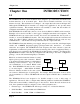
Chapter One Chapter One Introduction INTRODUCTION 1.1 General The WI-MOD-9-D radio modem module has been designed to provide flexible and reliable radio modem functions, at an economical price. Radio modems transmit serial data over a long distance via radio. The serial data is not changed - the output data is the same as the input data. Although the WI-MOD-9-D is intended to be simple in its application, it also provides many sophisticated features.
WI-MOD-9-D Radio Modem • User Manual v1.9 Operating mode - transparent mode or controlled mode . The operation of the WI-MOD-9-D radio modem is relatively simple. As data is received at the serial port, the data is transmitted on the radio channel. Up to 530 bytes of data can be transmitted in one transmission.
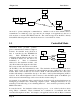
Chapter One Introduction PLC WI-MOD PLC PLC RS485 WI-MOD PLC WI-MOD Transpar ent mode is “point-to-multipoint” communications, suitable for a host device which is able to communicate on a multi-drop “bus” type network. An example of an application is the use of radio modems to extend a PLC RS485 network. The serial messages from the PLC’s already include PLC addressing and error detection/correction to control the flow of data. 1.
WI-MOD-9-D Radio Modem User Manual v1.9 to set destination addresses would be a central computer polling data loggers for periodic information. 1.4 Repeater Units A WI-MOD-9-D unit may be used as a repeater to re-transmit radio messages. The purpose of a repeater unit is to extend radio range. In transparent mode, there can be an unlimited number of repeaters, however with some conditions (refer to Section 3.5). The repeater in transparent mode will repeat every transmission it receives.
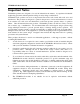
Chapter Two Chapter Two Installation INSTALLATION 2.1 General The WI-MOD-9-D module is housed in an rugged aluminum case, suitable for DIN-rail mounting. Terminals will accept wires up to 12 gauge (2.5 sqmm) in size. All connections to the module must be SELV. Normal 110-240V mains supply should not be connected to any terminal of the WI-MOD-9-D module. Refer to Section 2.3 Power Supply. Before installing a new system, it is preferable to bench test the complete system.
WI-MOD-9-D Radio Modem User Manual v1.9 Line-of-sight paths re only necessary to obtain the maximum range. Obstructions will reduce the range, however may not prevent a reliable path. A larger amount of obstruction can be tolerated for shorter distances. For very short distances, it is possible to mount the antennas inside buildings. An obstructed path requires testing to determine if the path will be reliable refer the section 6 of this manual.
Chapter Two Installation with another layer of PVC UV Stabilised insulating tape. The first layer of tape allows the joint to be easily inspected when trouble shooting as the vulcanising seal can be easily removed. Where antennas are mounted on elevated masts, the masts should be effectively earthed to avoid lightning surges. For high lightning risk areas, surge suppression devices between the module and the antenna are recommended.
WI-MOD-9-D Radio Modem User Manual v1.9 Yagi antennas are directional. That is, they have positive gain to the front of the antenna, but negative gain in other directions. Hence Yagi antennas should be installed with the central beam horizontal and must be pointed exactly in the direction of transmission to benefit from the gain of the antenna. The Yagi antennas may be installed with the elements in a vertical plane (vertically polarised) or in a horizontal plane (horizontally polarised).
Chapter Two Installation 2.3 Power Supply The WI-MOD-9-D module is powered by a 10 - 30VDC or 13 – 24VAC supply. The power supply should be rated at 1 Amp and be CSA Certified Class 2. For DC supplies, the negative side of the supply is connected to "COM" and may be connected to “ground”. The supply negative is connected to the “GND” terminal internally. The positive side of the supply must not be connected to earth. The DC supply may be a floating supply or negatively grounded.
WI-MOD-9-D Radio Modem User Manual v1.9 Example cable drawings for connection to a DTE host (a PC) or another DCE host (or modem) are detailed above.
Chapter Two Installation WI-MOD-9-D HOST HOST RS485 CONNECTIONS WI-MOD-9-D HOST HOST 120Ω DIP SWITCH FOR 120Ω SUPPLY RS485 RS232 - - + + + 120 Ω RS485 CONNECTION USING TERMINATING RESISTOR Page 17
WI-MOD-9-D Radio Modem User Manual v1.9 Chapter Three OPERATION 3.1 Power-up and Normal Operation When power is initially connected to the WI-MOD-9-D module, the module will perform internal diagnostics to check its functions. The following table details the status of the indicating LEDs on the front panel under normal operating conditions.
Chapter Three Operation When the WI-MOD-9-D unit detects data in the input buffer, it initiates a radio message. The radio message will end when the number of transmitted bytes reaches the maximum message length (configurable by the user), or if the input buffer becomes empty. If the configured serial data rate is the same or more than the radio data rate, then data is transmitted as soon as it enters the input buffer - data “streams” from the input buffer to the radio port.
WI-MOD-9-D Radio Modem 3.2.2 User Manual v1.9 Serial Data Rate The communications baud rates supported on both the RS232 serial port and the RS485 serial port are 1200, 2400, 4800, 9600, 14400, 19200, 28800, 31250, 38400, 57600, 76800 and 115200 baud the user selects one of these rates during the configuration of the modem. 3.2.3 Radio Data Rate The data is transmitted by radio as direct modulated synchronous data at 19200, 57600 or 115200 bits/second.
Chapter Three 3.3 Operation Addressing A WI-MOD-9-D network comprises modules with the same "system" address. Only modules with the same system address will communicate with each other. This feature allows more than one system to operate in the same area on the same radio channel. We recommend that you select a random number for the system address. In transparent mode, each module is also configured with a “group” address. A system may comprise several groups or sub-systems.
WI-MOD-9-D Radio Modem lead-in User Manual v1.9 system/group addr data error check (if configured) |---------------|-----------------|------------------------------------------|--------------| 30msec 2 bytes 1 ms @19.2Kb 0.5ms per byte @ 19.2Kb 2 bytes 1ms @ 19.2Kb If error checking is not configured at the receiving unit, data will start to be output approximately 1 msec after the system address has been received.
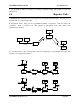
Chapter Three Operation Module A, B and C are configured as transparent repeaters. Module A is configured with group addresses 1 & 2, module B with group addresses 2 & 3 and module C with group addresses 3 & 4. Module S and T are configured with group address 1 (only one group address as it is not configured as a repeater). When S transmits a message, T and A will receive it and output the data. If module X can hear the message, it will not output it as module X is configured with group address 2.
WI-MOD-9-D Radio Modem User Manual v1.9 3.6 Controlled Mode In controlled mode, data is only transferred between two modules (that is, a point to point link). One of the modules is configured as a “master” unit and the other as a “slave” unit. There can also be up to five intermediate repeaters in the link. Each WI-MOD-9-D unit is configured with a unit address - only the unit with an address matching the destination address of the radio message will process the message and output the serial data.
Chapter Three Operation During normal operation, if there has been no radio activity for a period (called the “link check” period), the “master” unit will transmit the “connect” message to check the radio path. The link check period is a time configured by the user.
WI-MOD-9-D Radio Modem User Manual v1.9 approx 2msec after the end of the message. For example, a message with 20 bytes of data transmitted at 19200 bits/sec with no repeaters, will be output approx 44msec after the data is input, assuming that error checking is configured. There is a special configuration of controlled mode which provides a 5msec lead-in time for fast operation (see below). With the fast operation, the time to transmit 20 bytes at 19200 baud is less than 20 msec.
Chapter Three Operation The link is normally disconnected by the host issuing a disconnect command. In this mode, it is normal for a host to connect and disconnect to several slave modules using AT commands. A common example is a PC polling several analyzers or dataloggers. The PC connects to a remote station one at a time, transfers data, disconnects and connects to the next station. Up to five repeater addresses may be configured as part of the remote address.
WI-MOD-9-D Radio Modem Repeater Communications User Manual v1.
Chapter Three Operation We recommend that units in the same system have the same error-check configuration, however it is possible for users to configure the units differently. If a unit without error-check configured receives a message which includes an error-check, then the unit will treat the additional two bytes as data and output them to the host device.
WI-MOD-9-D Radio Modem User Manual v1.9 probability of two devices using the same channel is small, and if this does occur, probability of sharing the same channel on a re-transmission is extremely small. the There is a higher chance of interference from other WI-MOD-9-D systems. Because WI-MOD9-D are designed to operate in a peer-to-peer network, without a “master module” directing the communications, each WI-MOD-9-D will scan the radio band looking for other WI-MOD-9-D messages.
Chapter Three Operation If a system gives poor performance after it is installed, check the adequacy of the radio path refer to the Diagnostics Section 6. Interference will only cause a problem if the amplitude of the interference is comparable to the radio signal from the WI-MOD-9-D units. If the interference level is relatively small, then it will not affect the performance of the system.
WI-MOD-9-D Radio Modem User Manual v1.9 Chapter Four CONFIGURATION 4.1 Before Configuring Configuration comprises selecting parameter values for the operation of the WI-MOD-9-D unit. Four pre-set configurations may be achieved using the four DIP switches. These configurations cover most applications - refer section 4.7. Before you start configuration, parameter settings must be decided. The main parameters are:• Addressing - system address, group address, unit address. • Character type.
Chapter Four 4.2 Configuration Addressing A WI-MOD-9-D network comprises modules with the same "system" address. The system address is a 8 bit value (values 0 to 255). Only modules with the same system address will communicate with each other. If you are adding another module to an existing system, use the same value as the existing modules. If you are starting a new system, select random values and use the same value for each module. In transparent mode, a group address also needs to be configured.
WI-MOD-9-D Radio Modem User Manual v1.9 Reading and Configuring a module You will need a connection cable between the PC and the WI-MOD-9-D. The cable should have straight-through connections as per section 2.4.1 of this manual. If your PC only has USB serial connections with no RS232 port, you will need to purchase a USB to RS232 converter cable. WI-MOD-9-D Configuration Select the communications port that you will be using on the PC - make sure that no other program is using this com port.
Chapter Four Configuration Modifying an existing configuration If you read a configuration from a module or a saved file, the program will display the configuration parameters. You can change these parameters, and then program the module and/or save the file. WI-MOD-9-D Configuration 4.4.1 Transparent Mode The default setting of the program is transparent mode.
WI-MOD-9-D Radio Modem that module (1 – 127). Auto-Connect Master User Manual v1.9 WI-MOD-9-D Configuration In auto-connect mode, the “master” will automatically attempt to connect to the slave address. Once connected, the link can transfer data in either direction, with error-checking, acknowledgement messages, and automatic re-transmissions if necessary. If the link connection fails (indicated by the DCD led), then the master unit will automatically try to reconnect to the slave.
Chapter Four Configuration In fast operation mode, the master and slave modules continually communicate with each other (even if there is no data) to minimize radio synchronizing time when data is to be transmitted. You cannot use repeaters when using the option. Unit address should be less than 15.
WI-MOD-9-D Radio Modem User Manual v1.9 transmission delay parameters in registers S18 and S19 (refer section 3.8). To disable this, deselect the “PLC Mode” box in the Serial configuration window. CRC Error Checking It is normal for error checking to be disabled for transparent mode and enabled for controlled. However you can select either for either mode. Refer to section 3 of this manual for a description on the operation of error-checking.
Chapter Four “None” - The RTS signal from the host is ignored and the WI-MOD-9-D sets the CTS signal always on. Configuration WI-MOD-9-D Configuration “CTS/RTS” - input buffer flow control - the WI-MOD-9-D will reset the CTS signal when its input buffer is full - presently there is no flow control on the output side; if the host resets the RTS signal, the WI-MOD-9-D will still output data “RS-485” - must be selected if using the RS485 port; the WI-MOD-9-D resets CTS when it is transmitting data.
WI-MOD-9-D Radio Modem User Manual v1.9 “Pulse Low on Disconnect” - the DCD signal will be normally on but will switch off momentarily (for 0.1 sec) when the link is reset. Advanced Settings These settings may be adjusted if the host device is using AT commands - refer to Appendix A for an explanation of the different parameters. S Registers These are parameter registers settable by AT commands. They do not normally need to be changed. Refer to Appendix A for an explanation of these parameters. 4.
Chapter Four Configuration Note that some commands will automatically exit command mode. Several commands can be run together, for example, ATB2&WO is the same as ATB2 and AT&W and ATO Prior to Configuration Before configuring a module initially, force the module to its factory default configuration either by using the DIP switches (refer section 4.3), or by using the AT&F command. If you are making a change to an existing configuration, this step is not necessary.
WI-MOD-9-D Radio Modem User Manual v1.9 Transparent mode If you have forced the module to factory default configuration, this configuration will not be necessary. The following commands can be used to change the configuration to transparent mode. AT&M0&L1 Transparent repeater AT&M1&L1 The repeater will use both a primary group address (AT&G) and a secondary group address (AT&U). Data will be output to the serial port only when received with the primary group address.
Chapter Four Configuration The module starts up in command mode and waits for a command from the host device. An ATD command will initiate a connect command to another module. HOST WI-MOD #5 WI-MOD #8 HOST For example, ATD8 to module #5 will initiate a connect command to be sent to module #8. Module #5 will respond with RINGING to its host. If #8 is not already connected to another module, it will connect (set DCD) and respond to #5.
WI-MOD-9-D Radio Modem User Manual v1.9 Controlled Mode Link Check and Reset times If the master module has not sent or received a radio message within a preset time, it will send a check message to make sure that the link is still active. If it does not receive a response from the slave unit, it will disconnect the link and reset DCD. The check time can be configured using the ATS6 command. For example, ATS6=10 sets the check time to 10 sec.
Chapter Four Configuration &V1 Only show settings that are different from the defaults. &V10 Display the Stored / Non-volatile Configuration. &V11 Display the elements of the stored configuration which differ from factory default. The WI-MOD-9-D has two sets of configuration parameters - a set stored in non-volatile memory and an active set in RAM memory. Normally on start-up, the configuration is read from the stored memory to the active memory.
WI-MOD-9-D Radio Modem Set the group address User Manual v1.9 AT&G1 The group address for the left hand side modules has been set to 1. Set the serial data rate to 38400 ATC6 Set the radio data rate to 19200 not necessary (default) Set the character type to 7,1,2,even AT&B13 Exit and save the configuration AT&W ATO The operating mode will already be in transparent mode from the factory default settings. The other default values for the other parameters will likely be OK.
Chapter Four Configuration Controlled Mode Source Repeater Repeater Destination #1 ----------------> #2 -----------------> #100 --------------------> #3 #101 Apart from being a repeater in the 1 - 3 link, 100 is also in a separate link to 101 Auto-connect link with repeaters Assume that default settings are used for data rates and character types. The only configuration required is addressing.
WI-MOD-9-D Radio Modem User Manual v1.9 Module #100 Note that #100 is the master unit for a link between #100 and #101, It is also acting as repeater in the #1 to #3 link. The system address for #100 and #101 must be the same as the other modules so that #100 can act as a repeater.
Chapter Four Configuration Switch Function 0000 Normal Operation – no change 0100 Restore Factory Defaults. AT&F 1100 Perform Transmit BER Test AT&T0 (for use with AT&T1 at other module - see section 6.2.1) Serial Radio 0010 Transparent Mode. AT&M0B0C4&L1 9600 19200 1010 “ AT&M0B1C6&L1 19200 57600 0110 “ AT&M0B1C9&L1 38400 57600 1110 “ AT&M0B2C10&L1 57600 115200 0001 Fast Controlled Mode, Autoconnect master.
WI-MOD-9-D Radio Modem User Manual v1.9 Chapter Five SPECIFICATIONS General EMC specification FCC Part 15 EN 300 683 89/336/EEC AS 3548 Radio specification Housing FCC Part 15.427 902 – 928MHz, 1W AS 4268.2 915 – 928MHz, 1W RFS29 NZ 920 – 928MHz, 1W 110 x 185 x 30mm Powder-coated, extruded aluminium DIN rail mount Terminal blocks Removable Suitable for 12 gauge (2.
Chapter Five Specifications Signal detect / RSSI -120 to -60 dBm Expected line-of-sight range USA / Canada 20+ miles Australia / NZ 20+ km Range based on 19200 baud. At 57600 baud, expected range is 60%, at 115200 baud, expected range is 30%.
WI-MOD-9-D Radio Modem User Manual v1.9 Chapter Six TROUBLESHOOTING 6.
Chapter Six Troubleshooting statistics. &T2 Transmit & Receive BER Test. Used with a second module configured as a transparent repeater. &T3 RSSI Measurement. Monitors the received signal strength, and displays in dBm. Most radio tests are carried out using the AT&T2 test as this is the easiest to accomplish. AT&T3 - Received Signal Strength Display This option provides for testing the radio path between two WI-MOD-9-D units.
WI-MOD-9-D Radio Modem User Manual v1.9 An example of the receiving unit’s display is here. Test 109 Errors 0 Extra 0 Level TotErr -77dBm 3 TotMissed 0 TotTest 109 kbit Test - the sequence number of the last received frame Errors - the number of bit errors in the last received frame Extra - any extra characters at the end of the frame (negative numbers indicate frame dropped out early) Level - the RSSI level when the frame was received.
Appendix A Hayes Commands Chapter Seven WARRANTY & SERVICE Weidmuller products are warranted to be free from manufacturing defects for a period of 24 months from the effective date of purchase. The effective date of purchase is decided solely by Weidmuller.
WI-MOD-9-D Radio Modem User Manual v1.9 Appendix A Hayes Commands The following details all of the Hayes commands supported by the WI-MOD-9-D.
Appendix A Hayes Commands ATSn? Read value from S-Register n, see description of S registers later in this section ATSn=xx Set value of S-Register n to xx ATV Verbal/Numeric Response Codes V0 Numeric response codes V1• Verbose response codes ATX Extended Response Codes. Allows more detailed response codes, including connection speed.
WI-MOD-9-D Radio Modem &E1 User Manual v1.9 Enable CRC Error Checking AT&F Restore Factory Defaults. This function is also available from the DIP Switches. AT&G Set module’s Group Address Range 0-255. Default 0. AT&K Flow Control Configuration. &K0 Flow Control Disabled. CTS Always high. Module ignores RTS. &K1 not used &K2 not used &K3 CTS/RTS Flow Control. CTS Reflects the state of the local buffer. Module only transmits serial data when RTS is high. &K4• RS-485 Control.
Appendix A Hayes Commands If a key is hit or a character input while attempting to connect, abort the connection attempt and return to command mode. &N1• AT&S Set module’s System Address Range 0-255. AT&T Self Tests. Allows in-field diagnostics, and factory testing. &T0 Transmit Bit Error Rate Test. Generates pseudo random data and sends out radio. &T1 Receive Bit Error Rate Test. Receives data from &T0 module, and records BER statistics. &T2 Transmit & Receive BER Test.
WI-MOD-9-D Radio Modem User Manual v1.9 S2 1-255 Escape Sequence Character (ASCII code) Normally 43 = “+” S3 0-127 Carriage Return Character Normally 13 = S4 0-127 Line Feed Character Normally 10 = S5 0-127 Back Space Character Normally 8 = S6 0-255 Link Check Timer Units Seconds. 0 disables. How frequently to send a “Link Check” message. Usually set less than the timeout set by the AT\Tcommand. Default 0.
Appendix A Hayes Commands S16 0-255 Transmit Hold-off Time In msec (default = 0) S17 0-255 Receive Hold-off Time In msec (default = 0) S18 0-255 Input buffer delay Radio will not transmit until the number of characters in the input buffer = 2 x S18 value - see below S19 0-255 Input buffer delay override Override time in msec to override S18 delay - see below.
WI-MOD-9-D Radio Modem User Manual v1.9 Response Codes Response codes display the status of the module in response to user commands. The response code displayed depends on the ATV setting, the ATX setting and the ATQ setting. ATV0 selects numeric response codes. ATV1 selects verbal response codes. The ATXn command selects extended response codes. ATQ0 disables all response messages. ATQ1 enables response messages. The following table describes the messages.