
Instruction Manual

Chapter Three Operation
Page 25
During normal operation, if there has been no radio activity for a period (called the “link check”
period), the “master” unit will transmit the “connect” message to check the radio path. The link
check period is a time configured by the user.
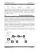
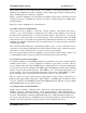
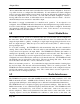
Successful Communications
Source Module Destination Module
• Serial data is received
• Serial RX LED flashes
• Listen to ensure channel is clear
• If clear, transmit message
• Radio TX LED flashes
-------->
• Receive message
• Radio RX LED flashes
• Check system and destination address
• If OK, check error-check
• Radio RX LED flashes
<--------
• If message okay, transmit back an ACK
message.
• Radio TX LED flashes
• Acknowledgment received okay
- communication complete
• Serial data is output
• Serial TX LED flashes
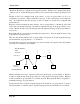
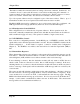
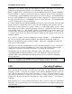
Unsuccessful Communications
Source Module Destination Module
• Listen to ensure channel is clear
• If clear, transmit message
• TX LED flashes
--------->
• Receives message
• RX LED flashes
• Check system and destination address
• If incorrect, transmit no message and no
serial output.
• No ACK received
• Retry up to four times
--------->
• If no ACK message received
after five attempts
• “NO CARRIER” message sent
to host
• DCD signal and DCD LED reset
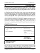
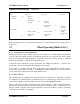
The time taken to transmit a message is :-
|------------HEADER-------------|--------------------DATA-----------|-----------|
lead-in system unit repeater dest. zero data error check
30msec address addr addrs's addr byte
No. of bytes 2 1 0 - 5 1 1 no. of data bytes 2
The time for each byte is 0.5msec @19200 bits/sec. The lead-in in fast-operation mode is only
5msec.
If error checking is not configured at the receiving unit, data will start to be output approx 1msec
after the "zero" byte has been received. If error checking is configured, data will be output