
Instruction Manual

WI-MOD-9-D Radio Modem User Manual v1.9
WI-MOD-9-D Manual v 1.9 Page 52
Chapter Six TROUBLESHOOTING
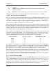
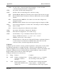
6.1 Diagnostics Chart
INDICATOR CONDITION MEANING
OK LED OFF Continuously
• Power supply failure
• CPU failure
OK LED ON Continuously
• Normal Operation
Radio TX LED ON Flashes briefly
• Radio transmitting
Radio RX LED ON GREEN flash
RED flash
• Radio receiving data
• Weak radio signal (< -95dBm)
Serial RX LED ON GREEN flash
RED flash
• Serial Port Receiving
• Input buffer almost full
Serial TX LED ON Flashes briefly
• Serial port transmitting
DCD LED ON Continuously
• In transparent mode, always on.
• In controlled mode, a radio link
has been established.
The green OK LED on the front panel indicates correct operation of the unit. This LED
extinguishes on failure as described above. When the OK LED extinguishes shutdown state is
indicated. On processor failure, or on failure during startup diagnostics, the unit shuts down, and
remains in shutdown until the fault is rectified.
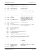
6.2 Test Functions
6.2.1 Radio Testing - AT&Tx
To aid in the checking and setup of the WI-MOD-9-D unit, diagnostic functions are provided
using the standard Hayes AT commands. To perform the tests, you will need a terminal (PC +
hyper-terminal) set-up to match the module (same character type and serial speed). The table
below outlines the functions of the various tests:
AT&T Self Tests. Allows in-field diagnostics, and factory testing.
&T0 Transmit Bit Error Rate Test. Generates pseudo random data and sends out radio.
&T1 Receive Bit Error Rate Test. Receives data from &T0 module, and displays BER