
User Guide

Part number 550-142-055/0411
GV90+ gas-fired water boiler — User’s Information Manual
10
1 Integrated boiler control
Theintegratedboilercontrol(IBC)respondstosignalsfromtheroomthermostat,air
pressureswitch,inletwatersensorandboilerlimitcircuittooperatethecirculators,
gasvalve,igniterandblower.Whenaroomthermostatcallsforheat,theIBCstartsthe
systemcirculatorandblower.
TheIBCrunstheblowertopurgetheboileruepassages,thenturnsontheigniterand
letsitwarmup.
Afterigniterwarm-up,theIBCopensthegasvalve,turnstheigniteroff,andchecksfor
ame.Theamemustcomeonwithin4secondsortheIBCwillshutdownandtrythe
full cycle again.
Whentheroomthermostatissatised,theIBCturnsofftheboilercomponentsand
waitsforthenextheatcall.
TheIBCindicatorlightsshownormalsequencewhenthelightsareonsteady.Whena
problemoccurs,theIBCashescombinationsoflightswhichindicatethemostlikely
reason for the problem.
2 Transformer
Thecontroltransformerreduceslinevoltageto24voltsforthegasvalveandlimitcircuit.
3 Blower
Theblowerpullsinairandmixesitwithgasfromthegasvalve.Theblowerforcesthis
mixture into the burner for combustion inside the boiler chamber.
4 Recuperator
Therecuperatorisastainlesssteelheatexchangerthatincreasesboilerefciencybyex-
tractingadditionalheatfromtheuegases.Returnwaterpassesthroughtherecuperator
before entering the boiler.
5 Water temperature limit switch
Thewatertemperaturelimitswitchturnsoffthegasvalveifthe temperatureinthe
boilergoesaboveitssetting.(Thecirculatorswillcontinuetorunaslongasthereisa
call for heat.)
6 System circulator
Thesystemcirculatorcirculateswaterthroughtheexternal(system)piping.Theow
rateofthecirculatoriscontrolledbytheIBC,dependingonthetemperatureofthewater
entering the boiler sections. Pump must remain on boiler — do not remove.
7 Bypass circulator
TheIBCoperatesthebypasscirculatortomixhotwaterfromtheboileroutletwith
colderreturnwaterfromthesystemasneededtopreventcondensationofuegasesin
the cast iron heat exchanger.
Whenthewaterreturning totheboilerisbelow140°F,theIBC regulatesthebypass
circulatorandsystemcirculatorowratestoraisethereturnwatertemperatureupto
140°Fbeforeitentersthecastironsections.Bybalancingtheseowrates,theIBCcan
protectagainstcondensationevenifreturnwaterisaslowas60°F.
Pump must remain on boiler — do not remove.
8 Air pressure switch
TheairpressureswitchsignalstheIBC,tellingthecontrolwhetherairismovingthrough
theblower.
9 Water temperature sensor
Thewatertemperaturesensormonitorsthetemperatureofthewaterenteringtheboiler
sections.ThesensorsendsthisinformationtotheIBC.TheIBCdetermineshowmuch
toadjustthecirculatorowratestoprovideatleast140°Fwatertothecastironheat
exchanger.
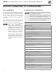
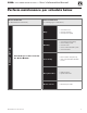
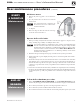
How it works . . .
LEGEND
a Supplytosystem,1”NPT
b Returnfromsystem,1”NPT
c Combustionair inlet tting —
3” PVC connection
d Flue outlet — 3” PVC connection
e Gas valve — negative pressure
regulated gas control
f Pressure/temperature gauge
g Fluewayinspectionportcover
h Sensor hose trap
i Manualairvent
j Relief valve
k Thermalfuse—aone-timefuse
devicethatshutsboileroffifue
temperature exceeds its setpoint
m Condensate trap line — shipped
loosewithboiler,eldinstalled
n Condensate drain connection —
½” PVC female
Thisboileruses a negative-pressure-
regulated gas valve, set for an outlet
pressureapproximately–0.20” water
column.
DO NOT set the outlet pressure higher
than factory setting.