Gas-fired water boilers – Series 3 Featuring Flexibility Boiler Manual • Installation • Maintenance • Startup • Parts This manual must only be used by a qualified heating installer/service technician. Read all instructions, including this manual and all other information shipped with the boiler, before installing. Perform steps in the order given. Failure to comply could result in severe personal injury, death or substantial property damage.
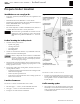
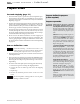
gas-fired water boiler The — Boiler Manual Gas-fired water boiler, Featuring 1. Cast aluminum heat exchanger 2. Heat exchanger access cover 3. Blower The advanced blower design and air inlet silencer on Ultra boilers result in very quiet operation. 16. U-Control Module The U-Control Module responds to signals from the room thermostats, DHW aquastats (when used), boiler sensors (boiler return, boiler supply, system return, system supply, flue temperature, and outdoor temperature, if used).
gas-fired water boiler The — Boiler Manual Gas-fired water boiler, Featuring Part number 550-100-066/0608 Flexibility 3
gas-fired water boiler — Boiler Manual Contents Hazard definitions . . . . . . . . . . . . . . . . . . . . 4 Gas piping . . . . . . . . . . . . . . . . . . . . . . . . 52 Please read before proceeding . . . . . . . . . . . . . 5 Field wiring . . . . . . . . . . . . . . . . . . . . . . . 54 Prepare boiler location . . . . . . . . . . . . . . . . . . 6 U-Control operation and setup . . . . . . . .
gas-fired water boiler — Boiler Manual Please read before proceeding Installer— Read all instructions, including this manual and all other information shipped with the boiler, before installing. Perform steps in the order given. Failure to adhere to the guidelines on this page can result in severe personal injury, death or substantial property damage. When servicing boiler — User — This manual is for use only by a qualified heating installer/service technician.
gas-fired water boiler — Boiler Manual Prepare boiler location Installations must comply with: • Local, state, provincial, and national codes, laws, regulations and ordinances. • National Fuel Gas Code, ANSI Z223.1 – latest edition. • Standard for Controls and Safety Devices for Automatically Fired Boilers, ANSI/ASME CSD-1, when required. • National Electrical Code. • For Canada only: B149.1 or B149.2 Installation Code, CSA C22.1 Canadian Electrical Code Part 1 and any local codes.
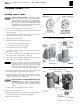
gas-fired water boiler — Boiler Manual Prepare boiler location (continued) Placing multiple boilers Figure 2 Side-to-side mounting of multiple Ultra boilers Figure 3 Back-to-back installation of multiple Ultra boilers Figure 4 Wall mounting multiple Ultra boilers 1. Locate multiple boilers in boiler room according to: a. Figure 2 (side-to-side), or b. Figure 3 (back-to-back). c. Figure 4 (wall mounting). 2. Provide indicated clearances around boilers for access and servicing.
gas-fired water boiler — Boiler Manual Prepare boiler location (continued) Flooring and foundation Provide air openings to room Flooring Air openings — Ultra boiler alone in boiler room 1. The Ultra boiler is approved for installation on combustible flooring, but must never be installed on carpeting. Do not install boiler on carpeting even if foundation is used. Fire can result, causing severe personal injury, death or substantial property damage. Foundation 1.
gas-fired water boiler — Boiler Manual Prepare boiler Vent and air piping (page 31) 1. The Ultra boiler requires a special vent system, designed for pressurized venting. Ultra boilers are rated ANSI Z21.13 Category IV (pressurized vent, likely to condense in the vent). See instructions beginning on page 31. 2. You must also install air piping from outside to the boiler air intake adapter. The resultant installation is categorized as direct vent (sealed combustion).
gas-fired water boiler — Boiler Manual Prepare boiler (continued) Installing propane orifice Figure 5 Orifice identification Figure 6 Installing propane orifice (Ultra-105 or Ultra-80LP ONLY) Figure 7 Installing propane orifice (Ultra-155, -210, -285, and -310) If boiler is already installed — You must turn off elec- trical supply to the boiler and close the external manual gas shut-off valve to isolate the boiler during conversion. Allow the boiler to cool if it has been operating.
gas-fired water boiler — Boiler Manual Prepare boiler (continued) Placing floor-mounted boilers Figure 8 Ultra-80 through Ultra-230 only — Install bottom-piping grommets if required Figure 9 Install wall-mount bracket 1. Set boiler in place and check level. a. Adjust legs, if necessary to level boiler. Wall-mounted boilers (Ultra-80 through -310) 1. The wall-mounting kit is NOT supplied as standard equipment with the boiler, and must be purchased separately. See WARNING below.
gas-fired water boiler — Boiler Manual Prepare boiler (continued) Prepare boiler for wall mounting 1. Remove the jacket front panel. This will simplify lifting and handling the boiler when mounting. 2. When piping will be routed out the top of the boiler, no special preparation is needed other than that given in this manual. 3. Ultra-80 to -230 only: To route the piping through the bottom of the boiler enclosure: a. Remove knockouts from bottom piping penetrations as shown in Figure 8, page 11. b.
gas-fired water boiler — Boiler Manual Prepare boiler (continued) DO NOT install a relief valve with a pressure higher than 30 PSIG. This is the maximum allowable relief Figure 12 Hydrostatic test piping connections valve setting for the Ultra boiler. Perform hydrostatic pressure test Pressure test boiler before permanently attaching water or gas piping or electrical supply. Prepare boiler for test 1. See Figure 12 for reference in following steps. 2.
gas-fired water boiler — Boiler Manual Install water piping Use two wrenches when tightening water piping at boiler, using one of the wrenches to prevent the boiler interior piping from turning. Failure to support the boiler piping connections to prevent them from turning could cause damage to boiler components. General piping information Additional controls, when required The U-Control module uses temperature sensors to provide both high limit protection and modulating temperature control.
gas-fired water boiler — Boiler Manual Install water piping (continued) System water piping methods Sizing system water piping All piping methods shown in this manual use primary/ secondary connection to the boiler loop. These designs ensure proper flow through the Ultra boiler, for the most efficient and reliable operation of the boiler and the heating system. For other piping methods, consult your local Weil-McLain representative or see separate Ultra boiler piping guides.
gas-fired water boiler — Boiler Manual Install water piping (continued) Expansion tank and make-up water Figure 14 Expansion tank piping 1. Ensure expansion tank size will handle boiler and system water volume and temperature. Allow 3 gallons for boiler and its piping. 2. 3. 4. 5. Undersized expansion tanks cause system water to be lost from relief valve and make-up water to be added through fill valve. Eventual boiler failure can result due to excessive make-up water addition.
gas-fired water boiler — Boiler Manual Install water piping (continued) Zoning with zone valves Figure 15 Zone valve zoning plus optional DHW piping 1. Connect boiler to system as shown in Figure 15 when zone valve zoning. The primary/secondary piping shown ensures the boiler loop will have sufficient flow. It also avoids applying the high head of the boiler circulator to the zone valves. 2.
gas-fired water boiler — Boiler Manual Install water piping (continued) Zoning with zone valves — alternate High-flow-rate/high-head-loss DHW circuits Figure 16 Zone valve zoning plus optional DHW piping 1. For applications requiring DHW circuit flow rates higher than allowable for the boiler, or for high pressure-drop coil-type DHW tanks, connect the piping as in Figure 16. The DHW water only flows through the secondary circuit connector piping.
gas-fired water boiler — Boiler Manual Install water piping (continued) Zoning with circulators Figure 17 Circulator zoning plus optional DHW piping 1. Connect boiler to system as shown in Figure 17 when circulator zoning. The boiler circulator cannot be used for a zone. It must supply only the boiler loop. 2. Install a separate circulator for each zone. 3. When using a closed-type expansion tank, connect the expansion tank and make-up water piping as shown in Figure 14, page 16. 4.
gas-fired water boiler — Boiler Manual Install water piping (continued) Radiant heating applications Figure 18 Typical radiant heating system piping plus optional DHW 1. The Ultra boiler is ideal for use in radiant heating. The Ultra boiler’s unique heat exchanger design allows it to work well even in condensing mode. So there is no need to regulate boiler return water temperature in radiant heating applications. 2. Connect boiler to system as shown in Figure 18 for typical radiant heating applications.
gas-fired water boiler — Boiler Manual Install water piping (continued) Chilled water systems Figure 19 Chilled water system plus optional DHW piping 1. Install boiler so that chilled medium is piped in parallel with the heating boiler. Use appropriate valves to prevent chilled medium from entering boiler. See Figure 19 for typical installation of balancing valve and check valve. 2. The space heating system may be zoned with circulators if a separate circulator is supplied for the chilled water loop.
gas-fired water boiler — Boiler Manual Install water piping (continued) Sizing DHW system piping For Weil-McLain PLUS water heaters — Refer to the installation manual for PLUS, GOLD PLUS, Ultra PLUS and other Weil-McLain heaters for application information. The information here is for other water heater designs.
gas-fired water boiler — Boiler Manual Install water piping (continued) Figure 22 Pipe sizing and head losses for DHW applications (H1=Ultra boiler head loss; Figure 23 Pump curves for typical circulators suggested for DHW loop H2=piping head loss) Flow rate Temp rise Pipe size H1 H2 GPM °F Inches Boiler head loss Feet w.c. Piping head loss Feet w.c. Ultra-80 (71,000 Btuh output) 3.5 (min) 41 1 1.4 0.8 7 20 1 6.6 2.7 9 16 1 11.6 4.2 10 14 1¼ 14.6 2.
gas-fired water boiler — Boiler Manual Multiple boiler water piping Easy-Fit® piping installation 1. Main header and Easy-Fit® Manifold pipe sizing. a. New system — See page 15. b. Replacing boilers in an existing system — Without reducing size, connect system supply and return lines. Install tees or crosses for Easy-Fit® manifolds as shown in Figure 24 or Figure 25. Size manifolds to handle total connected boiler output as shown. 2.
gas-fired water boiler — Boiler Manual Multiple boiler water piping (continued) Figure 26 Piping schematic — typical piping for multiple Ultra boilers, using Weil-McLain Easy-Fit manifolds Legend — Figure 26 1 Flow/check valve (each boiler) 2 Isolation valves (when used) 11 Check valve or backflow preventer, as required by applicable codes 12 Isolation valve 13 Cold water supply 3 Cap 4 Easy-Fit® Manifold (supply) — layout and size per page 24 5 Easy-Fit® Manifold (return) — layout and size per page 24
gas-fired water boiler — Boiler Manual Multiple boiler water piping (continued) Figure 27 Piping layout — typical piping for multiple Ultra boilers, using Weil-McLain Easy-Fit manifolds Legend — Figure 27 1 Flow/check valve (each boiler) 13 Cold water supply 3 Caps 17 Boiler circulator (each boiler) 4 Easy-Fit® Manifold (supply) — layout and size per page 24 18 System supply 5 Easy-Fit® Manifold (return) — layout and size per page 24 19 System return 6 Primary circulator 20 Boiler relief valve a
gas-fired water boiler — Boiler Manual Multiple boiler water piping (continued) Figure 28 Piping layout — typical piping for multiple Ultra boilers, with DHW storage heaters Suggested DHW boiler-side pipe sizing Flow rate Size Flow rate Size 0 – 7 gpm 1” 45–75 gpm 2½” 7 – 16 gpm 1¼” 75-140 gpm 3” 16 – 24 gpm 1½” 140–290 gpm 4” 24 – 45 gpm 2” Legend — Figure 28 1 2 3 4 5 6 7 8 9 13 17 18 19 20 Flow/check valve (each boiler) Isolation valves (when used) Caps Easy-Fit® Manifold (supply)
gas-fired water boiler — Boiler Manual Multiple boiler water piping (continued) Figure 29 Piping layout — typical piping for multiple Ultra boilers, using isolation exchanger Use isolation heat exchanger for: 1. Large volume systems with high mineral content in water. 2. Systems exposed to untreated quantities of makeup water. 3. Old systems severely contaminated with scale and rust buildup inside piping and heat distribution units. 4. Process applications. 5. Commercial service water applications. 6.
gas-fired water boiler — Boiler Manual Appliances remaining on an existing vent system Existing vent test procedure Do not install the Ultra boiler into a common vent with any other appliance. This will cause flue gas spillage or appliance malfunction, resulting in possible severe personal injury, death or substantial property damage. Existing common vent systems may be too large for the appliances remaining connected after the existing boiler is removed.
gas-fired water boiler — Boiler Manual Air piping — general You must pipe combustion air to the boiler air intake. The air termination fitting must be installed with the clearances and geometry relative to the vent outlet depicted in this manual to ensure that flue products do not enter the air intake. Ensure that the combustion air will not contain any of the contaminants in Figure 30. Do not pipe combustion air near a swimming pool, for example.
gas-fired water boiler — Boiler Manual Venting/air piping — general Ultra Boilers must be vented and supplied with combustion and ventilation air using piping and methods described in this manual. Every boiler must have its own vent. DO NOT common vent with any other appliance. See page 29. Inspect finished vent and air piping thoroughly to ensure all are airtight and comply with the instructions provided and with all requirements of applicable codes.
gas-fired water boiler — Boiler Manual Venting/air piping — general (continued) Vent and air pipe diameters Figure 34 Vent and air termination options 1.
gas-fired water boiler — Boiler Manual Sidewall vent/air termination: Weil-McLain plate Termination kit — Weil-McLain vent/air plate Figure 35 Maximum piping lengths for WeilMcLain sidewall vent/air plate 1. The Weil-McLain sidewall vent/air kit is shipped with each Ultra boiler. Provide pipe adapters as needed for 2” or 4” plastic piping or for AL29-4C vent pipe.
gas-fired water boiler — Boiler Manual Sidewall vent/air termination: Weil-McLain plate (continued) d. Avoid possibility of accidental contact of flue products with people or pets. e. Do not locate the terminations where wind eddies could affect performance or cause recirculation, such as inside building corners, near adjacent buildings or surfaces, window wells, stairwells, alcoves, courtyards or other recessed areas. f. Do not terminate above any door or window or under a deck.
gas-fired water boiler — Boiler Manual Sidewall vent/air termination: Weil-McLain plate (continued) c. Make sure there will be no obstructions that might prevent proper placement of the termination. d. Use the template to mark the locations for the four mounting holes, flue pipe and air pipe. Level the template with a spirit level.
gas-fired water boiler — Boiler Manual Sidewall vent/air termination: 3” PVC concentric Termination kit — Weil-McLain 3” PVC concentric termination 1. The Weil-McLain 3” PVC concentric termination kit must be purchased separately. See Figure 101, page 93 for part number.
gas-fired water boiler — Boiler Manual Sidewall vent/air termination: 3” PVC concentric (continued) b. The flue products will form a noticeable plume as they condense in cold air. Avoid areas where the plume could obstruct window views. c. Prevailing winds could cause freezing of condensate and water/ ice buildup where flue products impinge on building surfaces or plants. d. Avoid possibility of accidental contact of flue products with people or pets. e.
gas-fired water boiler — Boiler Manual Sidewall vent/air termination: 3” PVC concentric (continued) 2. Wall penetration — Preferably, use a thimble with a 4½-inch hole. If not using a thimble, carefully use a hole saw to cut a hole not larger than 4¾ inches in diameter through the wall. The finished hole must provide a solid stop for the rain cap ribs, as shown in the inset to Figure 47, page 38. Figure 47 Installing and supporting the concentric sidewall vent assembly 3.
gas-fired water boiler — Boiler Manual Sidewall vent/air termination: Separate pipes Allowable vent/air pipe materials Figure 48 Maximum piping lengths for separate vent and air pipe sidewall termination 1. Use only the materials listed in Figure 32, page 31. 2. Purchase termination plates and bird screens separately. See the parts list at the end of this manual.
gas-fired water boiler — Boiler Manual Sidewall vent/air termination: Separate pipes (continued) 4. You must consider the surroundings when terminating the vent and air: a. Position the vent termination where vapors will not damage nearby shrubs, plants or air conditioning equipment or be objectionable. b. The flue products will form a noticeable plume as they condense in cold air. Avoid areas where the plume could obstruct window views. c.
gas-fired water boiler — Boiler Manual Sidewall vent/air termination: Separate pipes (continued) 2. Place wall penetrations to obtain minimum clearance of 12 inches between vent pipe and adjacent air inlet elbow, as shown in Figure 52, page 40 for U. S. installations. Figure 53 Multiple terminations — separate pipes — clearance from vent of one to air intake of the next — alternate configuration of air and vent terminations 3. For Canadian installations, provide clearances required by CSA B149.
gas-fired water boiler — Boiler Manual Vertical vent/air termination: 3” PVC concentric Termination kit — Weil-McLain 3” PVC concentric termination 1. The Weil-McLain 3” PVC concentric termination kit must be purchased separately. See Figure 101, page 93 for part number. Use only the Weil-McLain 3” PVC concentric termination kit for concentric venting. Provide pipe adapters as needed for 2” or 4” plastic piping or for AL29-4C vent pipe.
gas-fired water boiler — Boiler Manual Vertical vent/air termination: 3” PVC concentric (continued) 4. Maintain clearances to termination as given below: a. Vent outlet must be located: • At least 6 feet from adjacent walls. • No closer than 5 feet below roof overhang. • At least 7 feet above any public walkway. • At lease 3 feet above any forced air intake within 10 feet. • No closer than 12 inches below or horizontally from any door or window or any other gravity air inlet. b.
gas-fired water boiler — Boiler Manual Vertical vent/air termination: 3” PVC concentric (continued) Figure 58 Weil-McLain 3” PVC concentric termination Figure 59 Weil-McLain 3” PVC concentric termination assembly assembly — DO NOT attach the rain cap until the termination has been inserted through the roof and all supports have been installed.
gas-fired water boiler — Boiler Manual Vertical vent/air termination: 3” PVC concentric (continued) 10. For each joint: a. Handle fittings and pipes carefully to prevent contamination of surfaces. b. Apply primer liberally to both joint surfaces — pipe end and fitting socket. c. While primer is still damp, lightly apply approved cement to both surfaces in a uniform coating. d. Apply a second coat to both surfaces. Avoid using too much cement on sockets to prevent cement buildup inside. e.
gas-fired water boiler — Boiler Manual Vertical vent/air termination: Separate pipes Allowable vent/air pipe materials Figure 62 Maximum piping lengths for separate vent and air pipe vertical termination 1. Use only the materials listed in Figure 32, page 31. 2. Purchase bird screens for vent and air terminations separately. See the parts list at the end of this manual.
gas-fired water boiler — Boiler Manual Vertical vent/air termination: Separate pipes (continued) 5. Maintain clearances to vent termination as given below: a. Vent must terminate: • At least 6 feet from adjacent walls. • No closer than 5 feet below roof overhang. • At least 7 feet above any public walkway. • At least 3 feet above any forced air intake within 10 feet. • No closer than 12 inches below or horizontally from any door or window or any other gravity air inlet. b.
gas-fired water boiler — Boiler Manual Install vent/air piping — boiler to termination Complete termination preparation Figure 65 Boiler vent and air connections 1. Install vent and air terminations before proceeding. See previous pages for instructions. Installing vent and air piping 1. For reference in the following see: a. Sidewall terminations: see Figure 66, page 49. b. Vertical terminations: see Figure 67, page 49. 2. Work from the boiler to vent or air termination.
gas-fired water boiler — Boiler Manual Install vent/air piping — boiler to terminations (continued) Figure 66 Sidewall termination methods and installation requirements Weil-McLain sidewall termination plate (install termination — page 33) Figure 67 Vertical termination methods and installation requirements Weil-McLain 3” PVC concentric termination (install termination — page 42) • Install pipe supports every 5 feet on both the horizontal and vertical runs.
gas-fired water boiler — Boiler Manual Install condensate line Prepare condensate fittings 1. Remove PVC fittings and gasket from the accessories bag. 2. Deburr and chamfer outside and inside of ½” x 1¼” PVC nipple to ensure even cement distribution when joining. 3. Clean nipple ends and all fittings. Dry thoroughly. 4. For each joint in the condensate line, apply the following. Assemble parts ONLY in the order given. a. Apply primer liberally to both joint surfaces — pipe end and fitting socket. b.
gas-fired water boiler — Boiler Manual Install condensate line (continued) 1. Connect condensate drain tubing to the ½” PVC tee and run to floor drain or condensate pump (see Figure 73). Use ½” PVC or CPVC pipe; or 5/8” I.D. tubing. Figure 71 Condensate drain — Ultra-155 & -230 (PVC tee installation shown applies to all models)) Use materials approved by the authority having jurisdiction. In the absence of other authority, PVC and CPVC pipe must comply with ASTM D1785, F441 or D2665.
gas-fired water boiler — Boiler Manual Gas piping Connecting gas supply piping 1. Remove jacket front panel and refer to Figure 74 to pipe gas to boiler. a. Install ground joint union for servicing, when required. b. Install manual shutoff valve in gas supply piping outside boiler jacket when required by local codes or utility requirements. Use two wrenches when tightening gas piping at boiler, using one wrench to prevent the boiler gas line connection from turning.
gas-fired water boiler — Boiler Manual Gas piping (continued) Natural Gas: Figure 75 Common gas line for multiple boilers Pipe sizing for natural gas 1. Size gas piping from meter outlet to entrance of boiler in accordance with Figure 76 and Figure 77. 2. Use total input of all boilers. Divide total input in Btuh by 1,000 to obtain cubic feet per hour of natural gas. a. Pipe lengths in Figure 76 are equivalent length of straight pipe.
gas-fired water boiler Field wiring — Boiler Manual (see Figure 78 & Figure 79) ondary heat source when another heat source, such as a heat pump or another boiler is available. ELECTRICAL SHOCK HAZARD — For your safety, turn off electrical power supply at service entrance panel before making any electrical connections to avoid possible electric shock hazard. Failure to do so can cause severe personal injury or death. Wiring must be N.E.C. Class 1.
gas-fired water boiler Field wiring — Boiler Manual (see Figure 78 & Figure 79) (continued) Figure 78 Schematic wiring diagram — Ultra-80 through Ultra-310 Part number 550-100-066/0608 55
gas-fired water boiler Field wiring — Boiler Manual (see Figure 78 & Figure 79) (continued) Figure 79 Ladder wiring diagram — Ultra-80 through Ultra-310 56 Part number 550-100-066/0608
gas-fired water boiler Field wiring — Boiler Manual (see Figure 78 & Figure 79) (continued) 2. You can connect any of the circulators you use to any of the three circulator activation terminals. The U-Control setup allows you to assign which circulators activate on a call for heat (this can be customized for each of the heating systems supplied by the boiler). 3.
gas-fired water boiler Field wiring — Boiler Manual (see Figure 78 & Figure 79) (continued) Additional limits Outdoor temperature sensor 1. The U-Control allows connection of external limit controls, both for manual reset and for automatic reset operation of the U-Control. 2. Manual reset of the U-Control on limit action — Connect external limits across P13, terminals 1 and 2 if the U-Control is to require manual reset when a limit opens, even if the limit re-closes.
gas-fired water boiler — Boiler Manual U-Control operation and setup Temperature settings — You must ensure that the U- Control is set for the proper water temperatures for the system. Excessive water temperature can cause significant property damage in some applications. Multi-temperature systems — If the heating system includes circuits that require lower temperature water (radiant slab circuits, for example) as well as higher temperature circuits (DHW, finned tube baseboard, etc.
gas-fired water boiler — Boiler Manual U-Control operation and setup (continued) Figure 81 U-Control display and navigation 60 Part number 550-100-066/0608
gas-fired water boiler — Boiler Manual U-Control operation and setup (continued) Low-temperature systems (radiant slab, etc.) — DO NOT use the Ultra boiler control as the only means of water temperature regulation for low-temperature systems if higher-temperature systems are also supplied. EXPRESS SETUP — using default settings 1. The U-Control is factory programmed to supply a DHW circuit (control priority 1) and finned tube baseboard space heating (control priority 2).
gas-fired water boiler — Boiler Manual U-Control operation and setup (continued) 3. OFF — Function disabled. 4. Type 1 — This means the Ultra boiler is the primary heat source. a. When the Ultra boiler receives a call for heat, it begins its startup sequence and also starts a delay timer (set as ADD’L HEAT DEMAND TIME). b. When the delay timing is reached, the U-Control closes the the “Additional heat demand contact,” terminals P16 #6 and #7. Use this contact to start the next heat source. c.
gas-fired water boiler — Boiler Manual U-Control operation and setup (continued) Figure 84 U-Control system types and preset parameters System type Display Preset temperatures Note 8-character 3-char Max Target Temp Outdoor Temp for Max Target Min Target Temp Outdoor Temp for Min Target Fan-coil FAN-COIL FCL 190 0 140 70 Finned tube baseboard FIN BASE FTB 180 0 130 70 Cast iron baseboard IRN BASE CIB 180 0 120 70 Cast iron radiators RADIATOR CIR 180 0 120 70 Radiant –
gas-fired water boiler — Boiler Manual U-Control operation and setup (continued) Figure 85 U-Control menus (press and hold the UP and DOWN arrow keys for 5 seconds to enter contractor menus) Menus Next screen Next screen Next screen Next screen Follow information at the bottom of each screen to navigate to next/previous screen or enter/save data BOILER SETTINGS SYSTEM SETTINGS BOILER MODEL ##### 80 105 155 230 310 HIGH ALTITUDE ### NO YES WWSD SETTING °F ADJUST OUTDOOR °F ### ### ### ### A
gas-fired water boiler — Boiler Manual U-Control operation and setup (continued) Figure 85 U-Control menus, continued (press and hold the UP and DOWN arrow keys for 5 seconds to enter contractor menus) Menus Next screen Next screen Next screen Next screen Follow information at the bottom of each screen to navigate to next/previous screen or enter/save data SET DATE AND TIME SET HR/MIN/DAY/MN/YR DIAGNOSTICS TEMPERATURES STATUS: ########## SYSTEM SUPPLY: ###°F SYSTEM RETURN: ###°F BOILER OUT1: ###°
gas-fired water boiler — Boiler Manual U-Control operation and setup (continued) Figure 86 U-Control setup options (see Figure 85, page 64 for location in menu sequence) Menu/Item Units Low Value High Value Default Comment Boiler Settings Boiler Model 80, 105, 155, 230, 310 factory THIS MUST BE SET CORRECTLY FOR SAFE OPERATION. Adjusts blower speeds and flame sense (Display will show “HA” after the model number if high altitude has been selected, below.
gas-fired water boiler — Boiler Manual U-Control operation and setup (continued) Figure 86 U-Control setup options (see Figure 85, page 64 for location in menu sequence), continued Menu/Item Units Low Value High Value Default Comment Max On Time minutes off 240 30 Longest time boiler will satisfy this system before switching to an active lower priority Min On Time minutes off 240 15 Time boiler will satisfy this system before switching to the next active priority Boost Interval minutes
gas-fired water boiler — Boiler Manual U-Control operation and setup (continued) Figure 87 U-Control diagnostic information (see Figure 85, page 64 for location in menu sequence Menu/Item Units Low Value High Value Default Comment Diagnostics Temperatures Status Text data System Supply System Return Boiler Out1 Boiler Out2 Boiler In1 Flue1 Flue2 Outdoor °F °F °F °F °F °F °F °F data data data data data data data data Inputs Status Text data Priority 1 Priority 2 Priority 3 Analog Input Manua
gas-fired water boiler — Boiler Manual U-Control operation and setup (continued) Figure 87 U-Control diagnostic information (see Figure 85, page 64 for location in menu sequence), continued Menu/Item Manual Reset Auto Reset Inputs Outputs Temperatures Lockout History 3 Time & Date Status Manual Reset Auto Reset Inputs Outputs Temperatures Software Versions Display Main Micro Second Micro Manual Test Mode Status Target Modulation System Supply System Return Boiler Out Boiler In Flame Signal Blower Signal B
gas-fired water boiler — Boiler Manual Startup — fill the system Freeze protection (when used) Follow these guidelines to prevent possibility of severe personal injury, death or substantial property damage: NEVER use automotive or standard glycol antifreeze, even glycol made for hydronic systems. Use only freeze-prevention fluids recommended by Weil-McLain for application in Ultra Boiler systems. Thoroughly flush any system that has used glycol before installing the new Ultra boiler.
gas-fired water boiler — Boiler Manual Startup — fill the system (continued) Add the correct amount of antifreeze 1. Determine the freezing temperature needed (to protect against lowest likely temperature the system water will encounter). 2. Find the antifreeze concentration by volume needed for this temperature from the antifreeze manufacturer’s data. 3. Add up the volume (gallons) of all system piping and components, including the expansion tank and boiler. Boiler water content is listed on page 105.
gas-fired water boiler — Boiler Manual Startup — fill the system (continued) Clean the cast aluminum heat exchanger 1. In order for the efficiency of boilers to increase beyond the condensing limit, new materials have been introduced for the heat exchanger, including aluminum. Aluminum has excellent heat transfer characteristics and is light in weight. 2. These new materials also require cleaning solutions that differ from those used in conventional cast iron and steel boilers.
gas-fired water boiler — Boiler Manual Startup — final checks Check for gas leaks Before starting the boiler, and during initial operation, use a leak detector or smell near the floor and around the boiler for gas odorant or any unusual odor. Remove boiler front door and smell interior of boiler enclosure. Do not proceed with startup if there is any indication of a gas leak. Repair any leak at once. DO NOT adjust or attempt to measure gas valve outlet pressure.
gas-fired water boiler — Boiler Manual Startup — final checks (continued) ❏ Check system and boiler ❏ Check water piping 1. Check system piping for leaks. If found, shut down boiler and repair immediately. (See WARNING on page 72 regarding failure to repair leaks.) 2. Vent any remaining air from system using manual vents. Air in the system will interfere with circulation and cause heat distribution problems and noise. ❏ Check vent piping and air piping 1.
gas-fired water boiler — Boiler Manual Startup — final checks (continued) 7. Measure natural gas input: a. Operate boiler 10 minutes. b. Turn off other appliances. c. At natural gas meter, measure time (in seconds) required to use one cubic foot of gas. d. Calculate gas input: 8. 9. 10. 11. 12. Figure 89 Throttle screw location (ONLY for use by a qualified technician, using calibrated combustion test instruments) e. Btuh calculated should approximate input rating on boiler rating label.
gas-fired water boiler — Boiler Manual U-Control operation and setup (continued) Figure 90 Operating instructions (WARNING — Verify that the U-Control is set for the correct boiler model before proceeding.
gas-fired water boiler — Boiler Manual Check-out/startup verification ❏❏ Verified that the U-Control is set for the correct boiler model? ❏❏ Boiler and heat distribution units filled with water? temperature requirements? Adjusted balancing valves and controls to provide design temperature to system? ❏❏ For multiple zones, adjusted for correct flow in each zone? ❏❏ Water chemistry verified per page 71? ❏❏ Verified thermostat heat anticipator (if available) set prop- ❏❏ Automatic air vents, if used, op
gas-fired water boiler — Boiler Manual Annual startup and general maintenance Figure 91 Service and maintenance schedules Service technician Owner maintenance (see following pages for instructions) (see Ultra User’s Information Manual for instructions) General: Reported problems Check boiler area Inspect interior; clean and vacuum if necessary; WARNING — no solvents Check air openings ANNUAL START-UP (See First-year special inspection) Clean condensate trap and fill with fresh water Daily Che
gas-fired water boiler — Boiler Manual Annual startup Handling ceramic fiber materials REMOVAL OF COMBUSTION CHAMBER LINING The combustion chamber lining in this product contains ceramic fiber material. Ceramic fibers can be converted to cristobalite in very high temperature applications. The International Agency for Research on Cancer (IARC) has concluded, “Crystalline silica inhaled in the form of quartz or cristobalite from occupational sources is carcinogenic to humans (Group 1).
gas-fired water boiler — Boiler Manual Annual startup (continued) Clean condensate trap The boiler should be inspected and started annually, at the beginning of the heating season, only by a qualified service technician. In addition, the maintenance and care of the boiler designated in Table 5 and explained on the following pages must be performed to assure maximum boiler efficiency and reliability. Failure to service and maintain the boiler and system could result in equipment failure.
gas-fired water boiler — Boiler Manual Annual startup (continued) 4. Inspect automatic air vents and air separators. Remove air vent caps and briefly press push valve to flush vent. Reinstall caps. Make sure vents do not leak. Replace any leaking vents. 5. Check system water chemistry (pH and hardness). See page 71. Check expansion tank 1. Expansion tanks provide space for water to move in and out as the heating system water expands due to temperature increase or contracts as the water cools.
gas-fired water boiler — Boiler Manual Annual startup (continued) Check burner flame The boiler contains ceramic fiber materials. Use care when handling these materials per instructions on page 79 of this manual. Failure to comply could result in severe personal injury. 1. Inspect flame through observation window using the procedure on page 74. 2. If flame is unsatisfactory at either high fire or low fire, turn off boiler and allow boiler to cool down.
gas-fired water boiler — Boiler Manual Annual startup (continued) 4. If flame signal still remains low, inspect the vent and air piping. Then inspect the heat exchanger, following the procedures given in this manual for removal and reinstallation of the head exchanger cover plate and other boiler components. Clean the exchanger as described in this manual if necessary. Check flue gas temperature 1. Set the boiler to high fire.
gas-fired water boiler — Boiler Manual Troubleshooting Label all wires prior to disconnection when servicing controls. Wiring errors can cause improper and dangerous operation. Always disconnect power to boiler before servicing. Failure to comply could result in severe personal injury, death or substantial property damage. Electrical shock hazard — The boiler ON/OFF switch does not turn off all power to the boiler. Internal wiring is still powered when the switch is off.
gas-fired water boiler — Boiler Manual Troubleshooting (continued) U-Control fault indications 1. The U-Control provides information for both automatic reset conditions and manual reset conditions. See Figure 87, page 68 for information available on the U-Control display. 3. Figure 95 shows the screen behavior during an automatic or manual reset condition. The table below the display illustration lists manual reset conditions and how to reset from them. Make sure to determine the causes of outages.
gas-fired water boiler — Boiler Manual Troubleshooting (continued) Figure 95 U-Control display toggles when in lockout, with screen flashing red to gray Message displayed Condition causing manual reset / lockout Reset action Manual reset limit open Heat exchanger temp high Supply water too fast Supply > return by 58 °F Temperature sensors Flue temperature high Flame fault Ignition fault Hardware fault Reset with manual reset on control Reset with manual reset on display Reset with manual reset on disp
gas-fired water boiler — Boiler Manual Troubleshooting (continued) Figure 96 Ultra wire harness details ( Pins Function = factory jumper) Wire ID / Color Pin — In Pin — Out Upper High Voltage Harness Wire ID / Color Pin — In Pin — Out Lower High Voltage Harness Wire ID / Color Pin - In P1: Pin 1 Power (120VAC): Hot 2 to 1 to 7 / Black 1 4 - Male Flange Connector 3 / Black 4 - Female Flange Connector 1 - Receptacle Hot P1: Pin 2 Power (120VAC): Neutral 3 to 6 / White 2 5 - Male Flange
gas-fired water boiler — Boiler Manual Troubleshooting (continued) Figure 96 Ultra wire harness details ( Pins Function = factory jumper), continued Wire ID / Color Pin — In Pin — Out Wire ID / Color Pin — In Pin — Out 591-391-946 Control / Display P9: Pin 1 RS485 A 1 / Brown 1 1 - Display RS485 A P9: Pin 2 RS485 B 2 / Orange 2 2 - Display RS485 B P9: Pin 3 Com 3 / Black 3 3 - Display Com P9: Pin 4 24VAC-R 4 / Red 4 4 - Display 24VAC-R P10: Pin 1 ODT Sensor: (+) P10: Pin 2 ODT S
gas-fired water boiler — Boiler Manual Maintenance Disconnect power Electrical shock hazard — Disconnect all electrical power to the boiler before attempting maintenance procedures. Failure to complete could result in severe personal injury, death or substantial property damage. Install boiler jacket front door after startup or servicing Reinstall boiler jacket front door after start-up or servicing.
gas-fired water boiler — Boiler Manual Maintenance (continued) Accessing & cleaning exchanger: Ultra-80 and Ultra-105 Only 1. Close the external manual gas valve. 2. Disconnect the flexible gas line at its flare fitting. Figure 97 Nut tightening sequence — 80 & 105 Gradually tighten the nuts, repeating the sequence shown below until the torque reaches 50 inch-pounds (+/- 10 inch-pounds) 3. Remove the air silencer by separating it from the air adapter on the blower inlet. 4.
gas-fired water boiler — Boiler Manual Maintenance (continued) Accessing & cleaning exchanger: Ultra-155, -230, and -310 Only 1. Close the external manual gas valve. 2. Disconnect wiring: • gas valve electrical plug • two electrical molex plugs from the blower assembly • ignition cable • ground wire. 3. Disconnect the flexible gas line at its flare fitting. 4. Remove the air silencer by lifting the plastic clamp off of the gas line and then gently sliding the air silencer down and off the valve. 5.
gas-fired water boiler — Boiler Manual Replacement parts Replacement parts must be purchased through a local Weil-McLain distributor. When ordering, specify boiler model and size and include description and part number of replacement part. Results from using modified or other manufactured parts will not be covered by warranty and may damage boiler or impair operation. Weil-McLain part numbers are found in Weil-McLain Boilers and Controls Repair Parts Lists. The boiler contains ceramic fiber materials.
gas-fired water boiler — Boiler Manual Replacement parts (continued) Figure 101 Miscellaneous parts and kits Item Description Part Number 1 Antifreeze, Alphi-11, 25 gallons 592-900-000 2 Boiler circulator, without flanges 3 Circulator hardware kit – inlet, 1” (1 flange, 2 nuts, 2 screws, and 1 gasket) (Ultra-80 to -230) 381-354-525 4 Circulator hardware kit (flange, nuts, screws, and gasket) 381-354-526 381-354-531 5 Concentric vent kit 383-500-350 6 Condensate neutralizer kit 383-
gas-fired water boiler — Boiler Manual Replacement parts (continued) Figure 102 Jacket parts Item Description Part Number 1 Jacket front door 383-500-135 2 Boiler leg kit 4 Required 383-500-065 3 Knurled head screw for jacket front door 2 Required 383-500-320 4 Knurled head screw clip-on receptacle (not shown) 2 Required 383-500-180 5 Air adapter assembly (Includes adapter, gasket and mounting bracket) Ultra-80 & -105, 3” Ultra-155, 3” Ultra-230 & -310, 4” 383-500-606 383-5
gas-fired water boiler — Boiler Manual Replacement parts (continued) Figure 103 Jacket parts Part number 550-100-066/0608 95
gas-fired water boiler — Boiler Manual Replacement parts (continued) Figure 104 Heat exchanger and piping — Ultra-80 and -105 Item Boiler Models Description 1 Heat exchanger replacement kit - Heat exchanger, cover plate, burner, electrode, water sensors, compression fittings, condensate fitting, gaskets, and hardware 2 Part Number Ultra-80NG Ultra-80LP Ultra-105 383-500-612 383-500-613 383-500-614 Cover plate replacement kit - Cover plate, cover plate gasket, burner gasket, and hardware Ultra-
gas-fired water boiler — Boiler Manual Replacement parts (continued) Figure 105 Heat exchanger and piping — Ultra-80 and -105 Part number 550-100-066/0608 97
gas-fired water boiler — Boiler Manual Replacement parts (continued) Figure 106 Heat exchanger and piping — Ultra-155 & -230 Item Boiler Models Description 1 Heat exchanger replacement kit - Heat exchanger, cover plate, burner, electrode, water sensors, compression fittings, condensate fitting, gaskets, and hardware 2 Part Number Ultra-155 Ultra-230 383-500-621 383-500-622 Cover plate replacement kit - Cover plate, cover plate gasket, burner gasket, and hardware Ultra-155/-230 383-500-395 3
gas-fired water boiler — Boiler Manual Replacement parts (continued) Figure 107 Heat exchanger and piping — Ultra-155 & -230 Part number 550-100-066/0608 99
gas-fired water boiler — Boiler Manual Replacement parts (continued) Figure 108 Heat exchanger and piping — Ultra-310 Item 1 Boiler Models Description Heat exchanger replacement kit - Heat exchanger, cover plate, burner, electrode, water sensors, compression fittings, condensate fitting, gaskets, and hardware Part Number Ultra-310 383-500-623 2 Cover plate replacement kit - Cover plate, cover plate gasket, burner gasket, and hardware Ultra-310 383-500-395 3 Cover plate insulation Ultra-310
gas-fired water boiler — Boiler Manual Replacement parts (continued) Figure 109 Heat exchanger and piping — Ultra-310 Part number 550-100-066/0608 101
gas-fired water boiler — Boiler Manual Replacement parts (continued) Figure 110 Controls Item Description Part Number 1 Ultra U-control module 383-500-627 2 Transformer, 120v/24v 383-500-628 3 Display board assembly (includes plastic and display screen) 383-500-629 4 On/off power switch 383-500-205 5 Pressure/temperature gauge assembly (Includes temperature and pressure sensor) 383-500-630 6 Flue temperature sensor replacement kit 383-500-600 7 System temperature sensors (2 required
gas-fired water boiler — Boiler Manual Replacement parts (continued) Figure 111 Controls Part number 550-100-066/0608 103
gas-fired water boiler — Boiler Manual Dimensions Figure 112 Dimensional data Notes 104 1 Boiler supply and return tappings are both 1” NPT (Ultra-80/105/155/230) or 1¼” NPT (Ultra-310). See page 15 for recommended piping sizes. Wall-hung boiler option — water piping and gas pipe can be routed through bottom of enclosure using wall-mounting kit. See page 6 for mounting instructions. 2 Boiler circulator is shipped loose. Circulator must be mounted in the return piping.
gas-fired water boiler — Boiler Manual Ratings — Ultra boilers Figure 113 Ratings and engineering data DOE Boiler Model Number DOE Heating Capacity CSA Input CSA Output Net I=B=R Ratings Boiler Water Content DOE Seasonal Efficiency Vent/Air Pipe Size Btuh (Note 2) Btuh (Note 7) Btuh (Note 7) Btuh (Note 3) Gallons AFUE, % (Note 1) (Note 4) Ultra-80 71,000 80,000 71,000 62,000 0.69 93.0 2” or 3” Ultra-105 94,000 105,000 94,000 81,000 0.82 92.
gas-fired water boiler — Boiler Manual Ratings — multiple Ultra boilers Figure 114 Ratings and engineering data (see Figure 116 for notes) DOE Boilers in system Model Ultra – 80 105 155 230 310 2 2 2 2 2 3 3 3 3 3 4 4 4 4 4 5 5 5 5 5 6 6 6 6 6 7 7 7 7 7 8 8 8 8 8 106 Manifolded combustion Net air duct water size ratings Total CSA input DOE Heating capacity Boiler H.P. Input, MBH Output, MBH - MBH Square inches - Note 1 - Note 2 Figure 31, page 30 160 142 4.
gas-fired water boiler — Boiler Manual Ratings — multiple Ultra boilers (continued) Figure 115 Engineering data (see Figure 116 for notes) Boiler Model Ultra – Shipping weight Pounds per boiler Operating weight Pounds per boiler Water content Gallons per boiler Water flow rate per boiler GPM @ 20°F rise GPM @ 40°F rise Vent/air pipe size — Provide a separate vent for each boiler Electrical service required Note 5 Note 6 Note 4 Amps per boiler 80 199 139 0.7 7.1 3.6 2” or 3” 15.
gas-fired water boiler 108 — Boiler Manual Part number 550-100-066/0608