Gas-fired water boilers – Series 3 Featuring ® Flexibility Manual addendum — Venting Supplementary instructions for: s Additional concentric vent/air termination kits, including IPEX System 636 in 3-inch and 4-inch sizes (for information on IPEX, go to www.ipexinc.com) s Direct exhaust venting (requires combustion air openings to boiler room/building per this addendum). s Direct vent with Roof exhaust and Sidewall air intake Contents Venting & air — general. . . . . . . . . . . . . . . . . . . . . . .
GAS-FIRED WATER BOILER — Manual addendum — Venting Venting & air — general Do not install the Ultra boiler into a common vent with any other appliance. This will cause flue gas spillage or appliance malfunction, resulting in possible severe personal injury, death or substantial property damage. Existing common vent systems may be too large for the appliances remaining connected after the existing boiler is removed.
GAS-FIRED WATER BOILER — Manual addendum — Venting Venting & air — general (cont.) Ultra Boilers must be vented and supplied with combustion and ventilation air using piping and methods described in this manual. Every boiler must have its own vent. DO NOT common vent with any other appliance. See page A-2. Inspect finished vent and air piping thoroughly to ensure all are airtight and comply with the instructions provided and with all requirements of applicable codes.
GAS-FIRED WATER BOILER — Manual addendum — Venting Venting & air — general (cont.
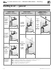
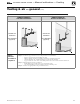
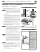
GAS-FIRED WATER BOILER — Manual addendum — Venting Venting & air — general (cont.) Figure 3 DIRECT EXHAUST APPLICATIONS — Vent termination options (combustion air from room) DIRECT EXHAUST Sidewall termination DIRECT EXHAUST Vertical termination Sidewall vent termination Vertical vent termination (See addendum page A-19) (See addendum page A-19) Direct exhaust installation sequence Step 1 Install the boiler. Step 2 Determine the proper location for roof or wall penetration for each termination.
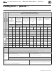
GAS-FIRED WATER BOILER — Manual addendum — Venting Venting & air — general (cont.) Figure 4 Vent and air pipe options and maximum allowable piping lengths t .BYJNVN FRVJWBMFOU GFFU PG QJQJOH t /VNCFS PG FMCPXT BMMPXFE BU UIFTF MFOHUIT Vent or air pipe size Ultra model (All applications include allowance for the terminations.
GAS-FIRED WATER BOILER — Manual addendum — Venting Venting & air — general (cont.
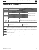
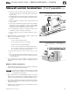
GAS-FIRED WATER BOILER — Manual addendum — Venting Sidewall vent/air termination: 3” or 4” concentric Termination kit — 3” or 4” PVC concentric termination Figure 6 Termination location — 3” or 4” PVC concentric termination — height above grade or snow line Figure 7 Termination location — 3” or 4” PVC concentric termination — clearances to openings 1. The 3” or 4” PVC concentric termination kit must be purchased separately. See below.
GAS-FIRED WATER BOILER — Manual addendum — Venting Sidewall vent/air termination: 3” or 4” concentric (cont.) b. The flue products will form a noticeable plume as they condense in cold air. Avoid areas where the plume could obstruct window views.
GAS-FIRED WATER BOILER — Manual addendum — Venting Sidewall vent/air termination: 3” or 4” concentric (cont.) Install terminations — concentric pipes 1. Assemble the vent termination as described for vertical concentric terminations, beginning on page A-12. Figure 10 Installing and supporting the concentric sidewall vent assembly If necessary, you can shorten the lengths of the inner and outer pipes for a shorter finished assembly. But you must ensure the pipes butt correctly at both ends.
GAS-FIRED WATER BOILER — Manual addendum — Venting Vertical vent/air termination: 3” or 4” concentric Termination kit — 3” or 4” PVC concentric termination Figure 12 Vertical termination — 3” or 4” PVC concentric 1. The 3” or 4” PVC concentric termination kit must be purchased separately. See below. Use only the vent materials and kits listed in Figure 2, page A-4 and Figure 4, page A-6 for concentric venting. Provide pipe adapters as specified in Figure 4, page A-6.
GAS-FIRED WATER BOILER — Manual addendum — Venting Vertical vent/air termination: 3” or 4” concentric (cont.) 4. Maintain clearances to termination as given below: a. Vent outlet must be located: s At least 6 feet from adjacent walls. s No closer than 5 feet below roof overhang. s At least 7 feet above any public walkway. s At lease 3 feet above any forced air intake within 10 feet. s No closer than 12 inches below or horizontally from any door or window or any other gravity air inlet. b.
GAS-FIRED WATER BOILER — Manual addendum — Venting Vertical vent/air termination: 3” or 4” concentric (cont.) When inserting the partially-assembled termination kit through the roof penetration, wrap plastic or other protection over the end of the exposed assembly to prevent debris from entering the pipes. If the air passages become blocked, the boiler will not operate. Once the rain cap has been cemented to the assembly, there is no way to correct the problem.
GAS-FIRED WATER BOILER — Manual addendum — Venting Concentric vent/air termination assembly Figure 17 3” or 4” PVC concentric termination assembly — DO NOT attach the rain cap until the termination has been inserted through the roof or wall and all supports have been installed.
GAS-FIRED WATER BOILER — Manual addendum — Venting DIRECT VENT: Vertical vent / sidewall air Allowable vent/air pipe materials Determine location 1. Use only the materials listed in Figure 5, page A-7. 2. Purchase bird screens for vent and air terminations separately. See the parts list at the end of this manual. 1. Locate the vent termination using the following guidelines: 2. The vent piping must terminate in an up-turned coupling as shown in Figure 20, page A-16.
GAS-FIRED WATER BOILER — Manual addendum — Venting DIRECT VENT: Vertical vent / sidewall air Termination and fittings 1. Prepare the vent termination coupling by inserting a bird screen. Bird screens must be purchased separately. See the parts list at the end of this manual for part numbers. a. If using 3-inch piping for an Ultra-230, cut a 4-inch bird screen by placing 3-inch fitting on screen and cutting around it as a template. 2.
GAS-FIRED WATER BOILER — Manual addendum — Venting DIRECT VENT: Vertical vent / sidewall air Multiple air terminations (continued) Figure 22 Sidewall air inlet installation for direct vent: vertical vent / sidewall air 1. When terminating multiple Ultra boiler air connections, terminate each air connection as described in this manual. 2. Place wall penetrations to obtain minimum clearances as instructed in this manual. 3. Place adjacent air inlets for multiple Ultra boilers at least 6 inches apart. 4.
GAS-FIRED WATER BOILER — Manual addendum — Venting Install vent/air piping — boiler to termination Complete termination preparation Figure 23 Boiler vent and air connections 1. Install vent and air terminations before proceeding. See previous pages for instructions. Installing vent and air piping 1. For reference in the following see: a. Sidewall terminations: see Figure 11, page A-10. b. Vertical terminations: see Figure 14, page A-13. 2. Work from the boiler to vent or air termination.
GAS-FIRED WATER BOILER — Manual addendum — Venting DIRECT EXHAUST venting — general Vent and air piping materials 1. See Figure 5, page A-7 for approved vent and air piping materials, for both direct exhaust and direct vent. SIDEWALL DIRECT EXHAUST Use the same vent or air piping material throughout. — Do not connect different types of piping to- gether. Vent piping 1.
GAS-FIRED WATER BOILER — Manual addendum — Venting DIRECT EXHAUST — Boiler room air openings Combustion air provision Special considerations The Ultra boiler can use inside air if no contaminants are present in the boiler space. (If contaminants are likely to be present, install the boiler as a direct vent appliance, using the appropriate vent instructions in this manual.) Tight construction ANSI Z223.
GAS-FIRED WATER BOILER — Manual addendum — Venting DIRECT EXHAUST — Boiler room air openings (continued) Figure 24 MINIMUM combustion air openings for direct exhaust applications — ALL OPENING SIZES ARE FREE AREA Air openings The required air opening sizes below are FREE AREA, after reduction for louver obstruction. Note the exception below for large spaces.
GAS-FIRED WATER BOILER — Manual addendum — Venting DIRECT EXHAUST — Sidewall Figure 25 DIRECT EXHAUST — Sidewall termination Allowable vent pipe materials 1. Use only the materials listed in Figure 5, page A-7. 2. Install a bird screen in each vent pipe termination (coupling or elbow). Bird screens are not supplied with the Ultra boiler. Purchase separately from Weil-McLain. Maximum piping length 1.
GAS-FIRED WATER BOILER — Manual addendum — Venting DIRECT EXHAUST — Sidewall (continued) Figure 26 DIRECT EXHAUST — Sidewall — configuration options and minimum clearances Figure 27 DIRECT EXHAUST — Sidewall — clearances to openings Figure 28 DIRECT EXHAUST — Sidewall — 4. Consider the surroundings when terminating the vent: a. Position the vent termination where vapors will not damage nearby shrubs, plants or air conditioning equipment or be objectionable. b.
GAS-FIRED WATER BOILER — Manual addendum — Venting DIRECT EXHAUST — Sidewall (continued) 8. Locate termination so it is not likely to be damaged by foreign objects, such as stones or balls, or subject to buildup of leaves or sediment. Figure 29 DIRECT EXHAUST — Sidewall — termination assembly — all parts by installer 9. Do not connect any other appliance to the vent pipe. Do not connect multiple boilers to a common vent pipe. Completing the vent piping 1.
GAS-FIRED WATER BOILER — Manual addendum — Venting DIRECT EXHAUST — Vertical Figure 30 DIRECT EXHAUST vertical termination Allowable vent pipe materials 1. Use only the materials listed in Figure 5, page A-7. 2. Install a bird screen in each vent pipe termination (coupling or elbow). Bird screens are not supplied with the Ultra boiler. Purchase separately from Weil-McLain. Maximum piping length 1.
GAS-FIRED WATER BOILER — Manual addendum — Venting DIRECT EXHAUST — Vertical (continued) Prepare roof penetration Figure 31 DIRECT EXHAUST — Vertical termination 1. Vent pipe penetration: a. Cut a hole for the vent pipe. For either combustible or noncombustible construction, size the vent pipe hole at least 0.5” larger than the vent pipe diameter: s 3” hole for 2” PVC. s 4” hole for 3” PVC. s 5” hole for 4” PVC. b. Insert a galvanized metal thimble in the vent pipe hole. 2.
GAS-FIRED WATER BOILER — Manual addendum — Venting Install vent — from boiler to termination Figure 32 Boiler vent and air connections (continued) Inserting/securing vent or air pipe into boiler connectors AL294C vent pipe — If using AL294C stainless vent pipe, you must install a PVC-to-vent pipe adapter at the boiler vent connection (and at the termination if using the Weil-McLain plate or the concentric termination). Use only the adapter made by the vent pipe manufacturer. 1.
GAS-FIRED WATER BOILER — Manual addendum — Venting