
Install Instructions (Venting)


Part number 550-100-103/1110
A–9
GAS-FIRED WATER BOILER — Manual addendum — Venting
Sidewall vent/air termination: 3” or 4” concentric (cont.)
The flue products will form a noticeable plume as they con-b.
dense in cold air. Avoid areas where the plume could obstruct
window views.
Prevailing winds could cause freezing of condensate and water/c.
ice buildup where flue products impinge on building surfaces
or plants.
Avoid possibility of accidental contact of flue products with d.
people or pets.
Do not locate the terminations where wind eddies could affect e.
performance or cause recirculation, such as inside building
corners, near adjacent buildings or surfaces, window wells,
stairwells, alcoves, courtyards or other recessed areas.
Do not terminate above any door or window or under a deck. f.
Condensate can freeze, causing ice formations.
Locate or guard vent to prevent condensate damage to exterior g.
finishes.
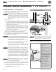
Maintain clearances as shown in 2. Figure 6, Figure 7, Figure 8 and
Figure 9. Also maintain the following:
Vent must terminate:a.
At least 6 feet from adjacent walls.s
No closer than 5 feet below roof overhang.s
At least 7 feet above any public walkway.s
At least 3 feet above any forced air intake within 10 feet.s
No closer than 12 inches below or horizontally from any s
door or window or any other gravity air inlet.
Air inlet must terminate at least 12” above grade or snow b.
line.
Do not terminate closer than 4 feet horizontally (above or be-c.
low) from any electric meter, gas meter, regulator, relief valve
or other equipment.
Locate terminations so they are not likely to be damaged by foreign 3.
objects, such as stones or balls, or subject to buildup of leaves or
sediment.
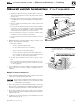
Multiple vent/air terminations
When terminating multiple Ultra boilers, terminate each vent/air 1.
connection as described in this addendum.
All vent pipes and air inlets must terminate at the same
height to avoid possibility of severe personal injury, death
or substantial property damage.
Place wall penetrations to obtain minimum clearance as shown in 2.
Figure 9 for U. S. installations. For Canadian installations, provide
clearances required by CSA B149.1 or B149.2 Installation Code.
The air inlet of an Ultra boiler is part of a direct vent connection. 3.
It is not classified as a forced air intake with regard to spacing from
adjacent boiler vents.
Combustion air (NOT vent piping) can be manifolded as shown 4.
in Boiler manual, page 55.
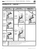
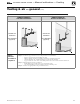
Termination location — 3” or 4” PVC Figure 8
concentric termination — clearances to
public walkway or forced air intake
Termination location — 3” or 4” PVC Figure 9
concentric termination — multiple boilers —
clearance from vent of one to air intake of the
next