Gas-fired water boilers – Series 4 Featuring Boiler Manual • Installation • Maintenance • Startup • Parts This manual must only be used by a qualified heating installer/service technician. Read all instructions, including this manual and all other information shipped with the boiler, before installing. Perform steps in the order given. Failure to comply could result in severe personal injury, death or substantial property damage.
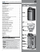
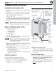
series 4 gas-fired water boiler Contents Ultra at-a-glance Hazard definitions & Ultra at-a-glance . . . . . . . . . . . . . . . . . . . . . 2 (see page 44 and page 46 for details of all models) Please read before proceeding . . . . . . . . . . . . . . . . . . . . . . . . . . . . . . 4 Prepare boiler location . . . . . . . . . . . . . . . . . . . . . . . . . . . . . . 5 Prepare boiler . . . . . . . . . . . .
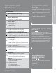
Quick view . . .
series 4 gas-fired water boiler – boiler manual Please read before proceeding Installer— Read all instructions, including this manual and all other information shipped with the boiler, before installing. Perform steps in the order given. User — This manual is for use only by a qualified heating installer/service technician. Refer to User’s Information Manual for your reference. User — Have this boiler serviced/inspected by a qualified service technician, at least annually.
series 4 gas-fired water boiler – boiler manual Installations must comply with: y Local, state, provincial, and national codes, laws, regulations and ordinances. y National Fuel Gas Code, ANSI Z223.1 /NFPA 54 – latest edition. y Standard for Controls and Safety Devices for Automatically Fired Boilers, ANSI/ASME CSD-1, when required. y National Electrical Code. y For Canada only: Natural Gas and Propane Installation Natural Gas and Propane Installation CAN/CSA B149.1 or B149.
series 4 gas-fired water boiler – boiler manual Prepare boiler location (continued) Flooring and foundation Provide air openings to room Flooring Air openings — Ultra boiler alone in boiler room The Ultra boiler is approved for installation on combustible flooring, but must never be installed on carpeting. Do not install boiler on carpeting even if foundation is used. Fire can result, causing severe personal injury, death or substantial property damage. Foundation 1.
series 4 gas-fired water boiler – boiler manual Vent and air piping (page 16) 1. The Ultra boiler requires a special vent system, designed for pressurized venting. Ultra boilers are rated ANSI Z21.13 Category IV (pressurized vent, likely to condense in the vent). See instructions beginning on page 16. 2. You must also install air piping from outside to the boiler air intake adapter. The resultant installation is categorized as direct vent (sealed combustion).
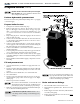
series 4 gas-fired water boiler – boiler manual Prepare boiler (continued) DO NOT install a relief valve with a pressure higher than 30 PSIG. This is the maximum allowable relief Figure 2 Hydrostatic test piping connections valve setting for the Ultra boiler. Perform hydrostatic pressure test Pressure test boiler before permanently attaching water or gas piping or electrical supply. Prepare boiler for test 1. See Figure 2 for reference in following steps. 2.
series 4 gas-fired water boiler – boiler manual Use two wrenches when tightening water piping at boiler, using one of the wrenches to prevent the boiler interior piping from turning. Failure to support the boiler piping connections to prevent them from turning could cause damage to boiler components. General piping information Additional controls, when required The U-Control module uses temperature sensors to provide both high limit protection and modulating temperature control.
series 4 gas-fired water boiler – boiler manual Install water piping (continued) System water piping methods Simplified pipe/circulator selection All piping methods shown in this manual use primary/ secondary connection to the boiler loop. These designs ensure proper flow through the Ultra boiler, for the most efficient and reliable operation of the boiler and the heating system. For other piping methods, consult your local WM Technologies representative or see separate Ultra boiler piping guides.
series 4 gas-fired water boiler – boiler manual Expansion tank and make-up water 1. Ensure expansion tank size will handle boiler and system water volume and temperature. Allow 3 gallons for boiler and its piping. 2. 3. 4. 5. Undersized expansion tanks cause system water to be lost from relief valve and make-up water to be added through fill valve. Eventual boiler failure can result due to excessive make-up water addition.
series 4 gas-fired water boiler – boiler manual Install water piping — typical systems Zoning with zone valves Figure 5 Zone valve zoning plus optional DHW piping 1. Connect boiler to system as shown in Figure 5 when zone valve zoning. The primary/secondary piping shown ensures the boiler loop will have sufficient flow. It also avoids applying the high head of the boiler circulator to the zone valves. Also see the information on page 14 and page 15 for suggested piping and sizing.
series 4 gas-fired water boiler – boiler manual Zoning with circulators Figure 6 BASIC INSTALLATION Install water piping — typical systems (continued) Circulator zoning plus optional DHW piping 1. Connect boiler to system as shown in Figure 6 when circulator zoning. The boiler circulator cannot be used for a zone. It must supply only the boiler loop. Also see the information on page 14 and page 15 for suggested piping and sizing.
series 4 gas-fired water boiler – boiler manual Using with Weil-McLain AQUA PLUS water heaters See AQUA PLUS - Product Manual for typical water piping. See ADVANCED INSTALLATION section for additional piping information and applications.
gas-fired water boiler – boiler manual 4 Using with Weil-McLain AQUA PLUS water heaters (cont.) See AQUA PLUS - Product Manual for typical water piping.
series 4 gas-fired water boiler – boiler manual Venting/air piping — general Do not install the Ultra boiler into a common vent with any other appliance. This will cause flue gas spillage or appliance malfunction, resulting in possible severe personal injury, death or substantial property damage. Existing common vent systems may be too large for the appliances remaining connected after the existing boiler is removed.
series 4 gas-fired water boiler – boiler manual Ultra Boilers must be vented and supplied with combustion and ventilation air using piping and methods described in this manual. Every boiler must have its own vent. DO NOT common vent with any other appliance. See page 16. Inspect finished vent and air piping thoroughly to ensure all are airtight and comply with the instructions provided and with all requirements of applicable codes.
series 4 gas-fired water boiler – boiler manual Venting & air — general (cont.) Figure 12 Vent and air pipe options and maximum allowable piping lengths • Maximum equivalent feet of piping • Number of elbows allowed at these lengths Vent or air pipe size Ultra model (All applications include allowance for the terminations.
series 4 gas-fired water boiler – boiler manual BASIC INSTALLATION Venting & air — general (cont.
series 4 gas-fired water boiler – boiler manual Sidewall vent/air termination: Separate pipes Allowable vent/air pipe materials 1. Use only the materials listed in Figure 13, page 19. 2. The Weil-McLain vent termination kit includes inside and outside wall plates, bird screens, and mounting hardware to secure the plates (kit included with boiler).
series 4 gas-fired water boiler – boiler manual 4. You must consider the surroundings when terminating the vent and air: a. Position the vent termination where vapors will not damage nearby shrubs, plants or air conditioning equipment or be objectionable. b. The flue products will form a noticeable plume as they condense in cold air. Avoid areas where the plume could obstruct window views. c.
series 4 gas-fired water boiler – boiler manual Sidewall vent/air termination: Separate pipes (continued) Multiple vent/air terminations 1. When terminating multiple Ultra boilers, terminate each vent/air connection as described in this manual. 2. 3. 4. 5.
series 4 gas-fired water boiler – boiler manual Allowable vent/air pipe materials Figure 21 Maximum piping lengths for separate vent and air pipe vertical termination 1. Use only the materials listed in Figure 13, page 19. 2. Purchase bird screens for vent and air terminations separately. See the parts list at the end of this manual.
series 4 gas-fired water boiler – boiler manual Vertical vent/air termination: Separate pipes (continued) 5. Maintain clearances to vent termination as given below: a. Vent must terminate: • At least 6 feet from adjacent walls. • No closer than 5 feet below roof overhang. • At least 7 feet above any public walkway. • At least 3 feet above any forced air intake within 10 feet. • No closer than 12 inches below or horizontally from any door or window or any other gravity air inlet. b.
series 4 gas-fired water boiler – boiler manual BASIC INSTALLATION DIRECT VENT Applications Figure 24 DIRECT VENT APPLICATIONS — Vent and air termination options DIRECT VENT SIDEWALL termination Weil-McLain sidewall termination cap DIRECT VENT VERTICAL vent and SIDEWALL air DIRECT VENT VERTICAL termination Vertical vent termination 3” or 4” concentric termination (See Boiler manual page 67) (See Boiler manual page 75) and AIR Sidewall air termination VENT AIR VENT (See Boiler manual page 7
series 4 gas-fired water boiler – boiler manual DIRECT EXHAUST Applications Figure 25 DIRECT EXHAUST APPLICATIONS — Vent termination options (combustion air from room) DIRECT EXHAUST Sidewall termination DIRECT EXHAUST Vertical termination Sidewall vent termination Vertical vent termination (See Boiler manual page 83) (See Boiler manual page 83) Direct exhaust installation sequence Step 1 Step 2 Step 3 Step 4 26 • • • • • • Install the boiler.
series 4 gas-fired water boiler – boiler manual Prepare condensate fittings 1. Remove PVC fittings and gasket from the accessories bag. 2. Deburr and chamfer outside and inside of ½” x 1¼” PVC nipple to ensure even cement distribution when joining. 3. Clean nipple ends and all fittings. Dry thoroughly. 4. For each joint in the condensate line, apply the following. Assemble parts ONLY in the order given. a. Apply primer liberally to both joint surfaces — pipe end and fitting socket. b.
series 4 gas-fired water boiler – boiler manual Install condensate line (continued) Condensate drain tubing Figure 30 Condensate drain — Ultra-155 & -230 (PVC tee 1. Connect condensate drain tubing to the ½” PVC tee and run to floor drain or condensate pump (see Figure 32). Use ½” PVC or CPVC pipe; or 5/8” I. D. tubing. installation shown applies to all models) Use materials approved by the authority having jurisdiction.
series 4 gas-fired water boiler – boiler manual Connecting gas supply piping 1. Remove jacket front panel and refer to Figure 33 to pipe gas to boiler. a. Install ground joint union for servicing, when required. b. Install manual shutoff valve in gas supply piping outside boiler jacket when required by local codes or utility requirements. c. In Canada — When using manual main shutoff valve, it must be identified by the installer. 2. Wall-mounted boilers a.
series 4 gas-fired water boiler – boiler manual Field wiring — basic system ELECTRICAL SHOCK HAZARD — For your safety, turn off electrical power supply at service entrance panel before making any electrical connections to avoid possible electric shock hazard. Failure to do so can cause severe personal injury or death. The installation must comply with: National Electrical Code and any other national, state, provincial or local codes or regulations. In Canada, CSA C22.
series 4 gas-fired water boiler – boiler manual BASIC INSTALLATION Field wiring — basic system (continued) Figure 34 Simplified wiring — basic system with DHW and space heating (see ADVANCED section for more information) Locate the sensors on the system piping as shown in Figure 4, page 11 and other piping drawings throughout this manual. Wire the DHW tank aquastat to the U-Control “heat demand 1” input, terminals P11 #4 and #5.
series 4 gas-fired water boiler – boiler manual U-Control operation and setup Temperature settings — You must ensure that the U-Control is set for the proper water temperatures for the system. Excessive water temperature can cause significant property damage in some applications. Multi-temperature systems — If the heating system includes circuits that require lower temperature water (radiant slab circuits, for example) as well as higher temperature circuits (DHW, finned tube baseboard, etc.
series 4 gas-fired water boiler – boiler manual 1 — Screen color (Blue = space heating or when a button is pressed) (Screen will show solid red, with the exclamation mark symbol, if a non-shutdown failure occurs; i.e., failure of a non-critical sensor, such as outdoor or system supply or return sensor.) H H : M M A M M M / D D / Y Y Time and date NO BACKLIGHT Figure 36 U-Control display and navigation H H : M M A M MODULATION (Pressing any button changes background to blue, below.
series 4 gas-fired water boiler – boiler manual U-Control operation and setup (continued) For detailed control information and additional wiring , see the ADVANCED INSTALLATION section of this manual. EXPRESS SETUP — using default settings 1. The U-Control is factory programmed to supply a DHW circuit (control priority 1) and finned tube baseboard space heating (control priority 2). 2.
series 4 gas-fired water boiler – boiler manual Clean system to remove sediment 1. You must thoroughly flush the system (without boiler connected) to remove sediment. The high-efficiency heat exchanger can be damaged by buildup or corrosion due to sediment. 2. For zoned systems, flush each zone separately through a purge valve. (If purge valves and isolation valves are not already installed, install them to properly clean the system.) 3.
series 4 gas-fired water boiler – boiler manual Startup — fill the system (continued) Freeze protection (when used) Follow these guidelines to prevent possibility of severe personal injury, death or substantial property damage: 3. Verify antifreeze concentration, when used. 4. Follow the instructions on the Sentinel test kit to sample the system water and verify inhibitor concentration. NEVER use automotive or standard glycol antifreeze, even glycol made for hydronic systems .
series 4 gas-fired water boiler – boiler manual Check for gas leaks Before starting the boiler, and during initial operation, use a leak detector or smell near the floor and around the boiler for gas odorant or any unusual odor. Remove boiler front door and smell interior of boiler enclosure. Do not proceed with startup if there is any indication of a gas leak. Repair any leak at once. DO NOT adjust or attempt to measure gas valve outlet pressure.
series 4 gas-fired water boiler – boiler manual Startup — final checks (continued) To start the boiler 1. Turn OFF the boiler ON/OFF switch. 2. R e a d a n d f o l l ow t h e O p e r at i n g In s t r u c t i on s , Figure 38, page 39. 3. The U-Control display will show installed sensors when first powered. Make sure the right sensors are detected. If not, determine the cause and correct before proceeding. 1. Check around the boiler for gas odor following the procedure of page 29 of this manual.
series 4 gas-fired water boiler – boiler manual BASIC INSTALLATION Startup — final checks (continued) Figure 38 Operating instructions (WARNING — Verify that the U-Control is set for the correct boiler model before proceeding.) FOR YOUR SAFETY READ BEFORE OPERATING If you do not follow these instructions exactly, a fire or explosion may result causing property damage, personal injury or loss of life. A. This appliance does not have a pilot.
series 4 gas-fired water boiler – boiler manual Startup — final checks (continued) Check flame & combustion with instruments For Ultra-399 propane boilers, special start-up is required. See page 41 for procedure. See DANGER on page 49 before proceeding. Figure 39 Models 80 & 105 — Throttle screw location (ONLY for use by a qualified technician, using calibrated combustion test instruments) 1. Initiate a call for heat on one of the heat demand inputs. 2.
series 4 gas-fired water boiler – boiler manual rubber grommet into the flue pipe, then insert the probe into the rubber grommet. Figure 41 Model 399 — Throttle screw location (ONLY for use by a qualified technician, using calibrated combustion test instruments) You must replace the flue gas temperature sensor to prevent flue gas spillage into the boiler enclosure. Failure to comply could result in severe personal injury, death or substantial property damage.
series 4 gas-fired water boiler – boiler manual Check-out/startup verification Verified that the U-Control is set for the correct boiler model? Entered installation date and installer contact information into U-Control? Boiler and heat distribution units filled with water? Water chemistry verified per page 35? Sentinel X100 corrosion inhibitor added and water tested to be within range? Automatic air vents, if used, open one full turn? Air purged from system? should be operating and s
4 gas-fired water boiler – boiler manual ADVANCED INSTALLATION (Pages 44–107) READ AND FOLLOW INSTRUCTIONS IN THE BASIC INSTALLATION SECTION FIRST. This section is supplemental information only. This section covers multiple boiler systems and system types not covered under the BASIC section. It also includes alternative vent/air piping methods, water and gas pipe sizing guidelines and advanced, detailed information on the U-Control and boiler wiring. ADVANCED INSTALLATION Quick view . . .
series 4 gas-fired water boiler – boiler manual The U ltra Gas-fired water boiler, Featuring U-Control Flexibility Ultra Models -80, -105, -155 and -230 1. Cast aluminum Nanogate coated heat exchanger 2. Heat exchanger access cover 3. Blower The advanced blower design and air inlet silencer on Ultra boilers result in very quiet operation.
series 4 gas-fired water boiler – boiler manual Gas-fired water boiler, Featuring The Flexibility Ultra-80 & 105 Front view (front door removed) (all models) 13 14 12 9 3 4c 11 24 7 25 4a 22 2 6 8 5 10 26 12 21 19 20 ADVANCED INSTALLATION 1 23 Ultra-155 & 230 Top view (all models) 13 Top is shown with top cover removed and control panel swung down for easy access to wiring terminals.
series The 4 gas-fired water boiler – boiler manual Gas-fired water boiler, Featuring Flexibility Ultra Models -299 and -399 1. Cast aluminum Nanogate coated heat exchanger 2. Heat exchanger access cover 3. Blower The advanced blower design and air inlet silencer on Ultra boilers result in very quiet operation. Air enters the boiler enclosure through the air intake adapter (18), flows through the enclosure, enters the air inlet silencer (5), then enters the venturi (6).
series gas-fired water boiler – boiler manual Gas-fired water boiler, Featuring Flexibility ADVANCED INSTALLATION The 4 Part number 550-100-440/0122 47
series 4 gas-fired water boiler – boiler manual Prepare boiler — convert for propane Prepare boiler for propane (when required) Propane operation Ultra boilers must be converted for propane operation unless specifically manufactured for propane. Propane-ready boilers have suffix “LP” after the model number. All other boilers require conversion for propane operation. Ultra-80 natural gas boilers require installation of a burner in addition to an orifice change.
series 4 gas-fired water boiler – boiler manual Prepare boiler — convert for propane (continued) Figure 45 Installing propane orifice (Ultra-155, -230, & -299) See Figure 43, page 48 or Figure 45. Inspect the O-ring between the gas valve and gas valve inlet adapter whenever they are disassembled. The O-ring must be in good condition and must be installed. Failure to comply will cause a gas leak, resulting in severe personal injury or death. 10.
series 4 gas-fired water boiler – boiler manual Placing boiler — wall-mounting option Wall-mounted boilers (Ultra-80 through -399) Figure 46 Install wall-mount bracket 1. The wall-mounting kit is NOT supplied as standard equipment with the boiler, and must be purchased separately. See WARNING below. Wall mount Ultra boilers only using the WeilMcLain Ultra boiler wall-mounting kit and accompanying instructions. (See Repair parts section for part number of wall mounting kit.
series 4 gas-fired water boiler – boiler manual Placing boiler — wall-mounting option (continued) Prepare boiler for wall mounting 1. Remove the jacket front panel. This will simplify lifting and handling the boiler when mounting. 2. When piping will be routed out the top of the boiler, no special preparation is needed other than that given in this manual. Install wall-mount bracket ADVANCED INSTALLATION 1. Locate studs. 2. Place the wall-mount bracket on the wall, using a level to align correctly. 3.
series 4 gas-fired water boiler – boiler manual Install water piping — advanced Zoning with zone valves Figure 48 (alternate to piping shown in Figure 5, page 12) Zone valve zoning plus optional DHW piping High-flow-rate/high-head-loss DHW circuits 1. For applications requiring DHW circuit flow rates higher than allowable for the boiler, or for high pressure-drop coil-type DHW tanks, connect the piping as in Figure 48. The DHW water only flows through the secondary circuit connector piping.
series 4 gas-fired water boiler – boiler manual Install water piping — advanced (continued) Example system with DHW as a zone, zoning with circulators Figure 49 Circulator zoning plus optional DHW piping 1. Connect boiler to system as shown in Figure 49 when circulator zoning. The boiler circulator cannot be used for a zone. It must supply only the boiler loop. Also see the information on page 10 for suggested piping and sizing.
series 4 gas-fired water boiler – boiler manual Install water piping — advanced (continued) Radiant heating applications 1. The Ultra boiler is ideal for use in radiant heating. The Ultra boiler’s unique heat exchanger design allows it to work well even in condensing mode. So there is no need to regulate boiler return water temperature in radiant heating applications. 2. Connect boiler to system as shown in Figure 50 for typical radiant heating applications.
series 4 gas-fired water boiler – boiler manual Install water piping — advanced (continued) Chilled water systems Figure 51 1. Install boiler so that chilled medium is piped in parallel with the heating boiler. Use appropriate valves to prevent chilled medium from entering boiler. See Figure 51 for typical installation of balancing valve and check valve.
series 4 gas-fired water boiler – boiler manual Sizing direct-connected DHW piping Direct-connected DHW piping For Weil-McLain AQUA PLUS water heaters, refer to the AQUA PLUS water heater manual for application information. Also see quick-select information on page 14. The information here is for other water heater designs.
series 4 gas-fired water boiler – boiler manual Sizing direct-connected DHW piping (continued) Figure 54 Pipe sizing and head losses for DHW applications (H1=Ultra boiler head loss; H2=piping head loss) Flow rate GPM Temp rise °F Pipe size Inches H1 Boiler head loss Feet w.c. H2 Piping head loss Feet w.c. Ultra-80 (71,000 Btuh output) 7 20 1 6.6 2.7 9 16 1 11.6 4.2 10 14 1¼ 14.6 2.
series 4 gas-fired water boiler – boiler manual Multiple boiler installations Placing multiple boilers Figure 56 Side-to-side mounting of multiple Ultra boilers 1. Locate multiple boilers in boiler room according to: a. Figure 56 (side-to-side), or b. Figure 57 (back-to-back). c. Figure 58 (wall mounting). 2. Provide indicated clearances around boilers for access and servicing. If recommended dimensions are not possible, provide at least the minimum clearances given on page 5. Also follow local codes.
series 4 gas-fired water boiler – boiler manual Multiple boiler installations (continued) Manifolded combustion air option 1. Multiple Ultra boilers can use a common combustion air manifold. a. See Figure 139, page 138 for minimum cross sectional area of combined air ducts. b. Provide minimum clearance to adjacent vents and grade/snow line as shown in Figure 59. c. Provide minimum free area in duct (adjusted for louver restriction) of 1 square inch per 2,000 Btuh total boiler input. d.
series 4 gas-fired water boiler – boiler manual Multiple boiler installations (continued) Easy-Fit® piping installation 1. Main header and Easy-Fit® Manifold pipe sizing. a. New system — See page 10. b. Replacing boilers in an existing system — Without reducing size, connect system supply and return lines. Install tees or crosses for Easy-Fit® manifolds as shown in Figure 60 or Figure 61. Size manifolds to handle total connected boiler output as shown. 2.
series 4 gas-fired water boiler – boiler manual Multiple boiler installations (continued) ADVANCED INSTALLATION Figure 62 Piping schematic — typical piping for multiple Ultra boilers, using Weil-McLain Easy-Fit manifolds Legend — Figure 62 1 Flow/check valve (each boiler) 2 Isolation valves (when used) 11 Check valve or backflow preventer, as required by applicable codes 12 Isolation valve 13 Cold water supply 3 Cap 4 Easy-Fit® Manifold (supply) — layout and size per page 60 5 Easy-Fit® Manifold (re
series 4 gas-fired water boiler – boiler manual Multiple boiler installations (continued) Figure 63 Piping layout — typical piping for multiple Ultra boilers, using Weil-McLain Easy-Fit manifolds (2-boiler system) Legend — Figure 63 1 2 3 4 5 6 7 8 9 13 17 62 Flow/check valve (each boiler) Isolation valves (when used) Caps Easy-Fit® Manifold (supply) — layout and size per page 60 Easy-Fit® Manifold (return) — layout and size per page 60 Primary circulator Expansion tank (diaphragm type) System air eli
series 4 gas-fired water boiler – boiler manual Multiple boiler installations (continued) Figure 64 Piping layout — typical piping for multiple Ultra boilers, with DHW storage heaters (4-boiler system) 2 19 30 28 4 30 5 2 9 3 8 6 27 2 2 18 13 1 7 1 2 26 17 17 20 2 20 31 20 2 2 2 17 2 17 1 25 2 1 31 20 31 ADVANCED INSTALLATION 2 31 Drain valves 22 21 24 22 24 29 21 23 21 Suggested DHW boiler-side pipe sizing (for max 0.
series 4 gas-fired water boiler – boiler manual Multiple boiler installations (continued) Figure 65 Piping layout — typical piping for multiple Ultra boilers, using isolation exchanger Use isolation heat exchanger for: 1. Large volume systems with high mineral content in water. 2. Systems exposed to untreated quantities of makeup water. 3. Old systems severely contaminated with scale and rust buildup inside piping and heat distribution units. 4. Process applications. 5.
series 4 gas-fired water boiler – boiler manual Venting/air piping — Massachusetts installations Commonwealth of Massachusetts Installations Commonwealth of Massachusetts — When the boiler is installed within the Commonwealth of Massachusetts, the boiler must be installed by a licensed plumber or gas fitter. Read and comply with the instructions below. 1. INSTALLATION OF CARBON MONOXIDE DETECTORS.
series 4 gas-fired water boiler – boiler manual Vent/air piping — options Vent and air pipe termination options 1. Vent and air piping must terminate out the sidewall or through the roof of the building, using only one of the methods described in this manual. 2. Sidewall options (see Figure 12, page 18, left side): a. TOP: Weil-McLain termination cap (kit included with boiler) — see page 67 for instructions. b. MIDDLE: Concentric PVC pipe (requires special kit, page 129). c.
series 4 gas-fired water boiler – boiler manual Sidewall vent/air termination: Weil-McLain cap Vent and air pipe termination options Vent and air pipe installation sequence 1. This section covers sidewall termination using the Weil-McLain sidewall vent cap. a. Models 80, 105 and 155 requires a 3-inch pipe size kit. b. Models 230, 299 and 399 requires a 4-inch pipe size kit. c.
series 4 gas-fired water boiler – boiler manual Sidewall vent/air termination: Weil-McLain cap (cont.) Provide pipe adapters as needed where pipe size is different from termination connections or boiler connections, and for all AL29-4C vent pipe connections at the boiler and the termination. Allowable vent/air pipe materials Maximum piping length 1.
series 4 gas-fired water boiler – boiler manual Sidewall vent/air termination: Weil-McLain cap (cont.) Figure 71 Termination location – Weil-McLain vent/air plate – clearances to openings Figure 72 Termination location – Weil-McLain vent/air plate – clearances to public walkway or forced air intake Multiple vent/air terminations 1. When terminating multiple Ultra boilers, terminate each vent/air connection as described in this manual.
series 4 gas-fired water boiler – boiler manual Sidewall vent/air termination: Weil-McLain cap (cont.) Install terminations — Weil-McLain vent/air cap Figure 74 Hole preparation in wall — Weil-McLain vent/air plate The inside and outside cover plates are stamped to identify the exhaust (vent) and intake (air) openings. Make sure to orient the plates correctly. 1. Locate termination opening and avoid obstructions: a. Use the template supplied with the termination kit. b.
series 4 gas-fired water boiler – boiler manual Install vent/air piping — boiler to W-M termination Complete termination preparation 1. Install vent and air terminations before proceeding. See previous pages for instructions.
series 4 gas-fired water boiler – boiler manual Sidewall vent/air termination: 3” or 4” concentric Termination kit — 3” or 4” concentric termination 1. The 3” or 4” concentric termination kit must be purchased separately. See below. Figure 78 Termination location — 3” or 4” concentric termination — height above grade or snow line Use only the vent materials and kits listed in Figure 12, page 18 for concentric venting. Provide pipe adapters as specified in Figure 12, page 18.
series 4 gas-fired water boiler – boiler manual Sidewall vent/air termination: 3” or 4” concentric (cont.) b. The flue products will form a noticeable plume as they condense in cold air. Avoid areas where the plume could obstruct window views. Figure 80 Termination location — 3” or 4” concentric termination — clearances to public walkway or forced air intake c. Prevailing winds could cause freezing of condensate and water/ ice buildup where flue products impinge on building surfaces or plants. d.
series 4 gas-fired water boiler – boiler manual Sidewall vent/air termination: 3” or 4” concentric (cont.) Install terminations — concentric pipes 1. Assemble the vent termination as described for vertical concentric terminations, beginning on page 76. Figure 82 Installing and supporting the concentric sidewall vent assembly If necessary, you can shorten the lengths of the inner and outer pipes for a shorter finished assembly. But you must ensure the pipes butt correctly at both ends.
series 4 gas-fired water boiler – boiler manual Vertical vent/air termination: 3” or 4” concentric Termination kit — 3” or 4” concentric termination 1. The 3” or 4” concentric termination kit must be purchased separately. See below. Figure 84 Vertical termination — 3” or 4” concentric Use only the vent materials and kits listed in Figure 12, page 18 for concentric venting. Provide pipe adapters as specified in Figure 12, page 18.
series 4 gas-fired water boiler – boiler manual Vertical vent/air termination: 3” or 4” concentric (cont.) • • • • At least 6 feet from adjacent walls. No closer than 5 feet below roof overhang. At least 7 feet above any public walkway. At lease 3 feet above any forced air intake within 10 feet. • No closer than 12 inches below or horizontally from any door or window or any other gravity air inlet. b. Air inlet must terminate at least 12 inches above the roof or snow line as shown in Figure 84, page 75.
series 4 gas-fired water boiler – boiler manual Vertical vent/air termination: 3” or 4” concentric (cont.) When inserting the partially-assembled termination kit through the roof penetration, wrap plastic or other protection over the end of the exposed assembly to prevent debris from entering the pipes. If the air passages become blocked, the boiler will not operate. Once the rain cap has been cemented to the assembly, there is no way to correct the problem.
series 4 gas-fired water boiler – boiler manual Concentric vent/air termination assembly Figure 89 3” or 4” concentric termination assembly — DO NOT attach the rain cap until the termination has been inserted through the roof or wall and all supports have been installed.
series 4 gas-fired water boiler – boiler manual DIRECT VENT: Vertical vent / sidewall air Allowable vent/air pipe materials Determine location 1. Use only the materials listed in Figure 13, page 19. 2. Purchase bird screens for vent and air terminations separately. See the parts list at the end of this manual. 1. Locate the vent termination using the following guidelines: Maximum piping lengths 3. You must consider the surroundings when terminating the vent and air: a.
series 4 gas-fired water boiler – boiler manual DIRECT VENT: Vertical vent / sidewall air Termination and fittings 1. Prepare the vent termination coupling by inserting a bird screen. Bird screens must be purchased separately. See the parts list at the end of this manual for part numbers. a. If using 3-inch piping for an Ultra-230, cut a 4-inch bird screen by placing 3-inch fitting on screen and cutting around it as a template. 2.
series 4 gas-fired water boiler – boiler manual DIRECT VENT: Vertical vent / sidewall air Multiple air terminations 1. When terminating multiple Ultra boiler air connections, terminate each air connection as described in this manual. 2. Place wall penetrations to obtain minimum clearances as instructed in this manual. 3. Place adjacent air inlets for multiple Ultra boilers at least 6 inches apart. 4. For Canadian installations, provide clearances required by CSA B149.1 or B149.2 Installation Code. 5.
series 4 gas-fired water boiler – boiler manual Install vent/air piping — boiler to termination Complete termination preparation Figure 95 Boiler vent and air connections 1. Install vent and air terminations before proceeding. See previous pages for instructions. Installing vent and air piping 1. For reference in the following see: a. Sidewall terminations: see Figure 105, page 92. b. Vertical terminations: see Figure 106, page 92. 2. Work from the boiler to vent or air termination.
series 4 gas-fired water boiler – boiler manual DIRECT EXHAUST venting — general Vent and air piping materials 1. See Figure 13, page 19 for approved vent and air piping materials, for both direct exhaust and direct vent. SIDEWALL DIRECT EXHAUST Use the same vent or air piping material throughout. — Do not connect different types of piping together. Vent piping 1.
series 4 gas-fired water boiler – boiler manual DIRECT EXHAUST — Boiler room air openings Combustion air provision Special considerations The Ultra boiler can use inside air if no contaminants are present in the boiler space. (If contaminants are likely to be present, install the boiler as a direct vent appliance, using the appropriate vent instructions in this manual.
series 4 gas-fired water boiler – boiler manual DIRECT EXHAUST — Boiler room air openings (continued) Air openings The required air opening sizes below are FREE AREA, after reduction for louver obstruction. Note the exception below for large spaces.
series 4 gas-fired water boiler – boiler manual DIRECT EXHAUST — Sidewall Figure 97 DIRECT EXHAUST — Sidewall termination Allowable vent pipe materials 1. Use only the materials listed in Figure 13, page 19. 2. Install a bird screen in each vent pipe termination (coupling or elbow). Bird screens are not supplied with the Ultra boiler. Purchase separately from WM Technologies. Maximum piping length 1.
series 4 gas-fired water boiler – boiler manual DIRECT EXHAUST — Sidewall (continued) minimum clearances Figure 99 DIRECT EXHAUST — Sidewall — clearances to openings Figure 100 DIRECT EXHAUST — Sidewall — clearances from 4. Consider the surroundings when terminating the vent: a. Position the vent termination where vapors will not damage nearby shrubs, plants or air conditioning equipment or be objectionable. b. The flue products will form a noticeable plume as they condense in cold air.
series 4 gas-fired water boiler – boiler manual DIRECT EXHAUST — Sidewall (continued) 8. Locate termination so it is not likely to be damaged by foreign objects, such as stones or balls, or subject to buildup of leaves or sediment. 9. Do not connect any other appliance to the vent pipe. Do not connect multiple boilers to a common vent pipe. Figure 101 DIRECT EXHAUST — Sidewall — termination assembly — all parts by installer Completing the vent piping 1.
series 4 gas-fired water boiler – boiler manual DIRECT EXHAUST — Vertical Figure 102 DIRECT EXHAUST vertical termination Allowable vent pipe materials 1. Use only the materials listed in Figure 13, page 19. 2. Install a bird screen in each vent pipe termination (coupling or elbow). Bird screens are not supplied with the Ultra boiler. Purchase separately from WM Technologies. Maximum piping length 1.
series 4 gas-fired water boiler – boiler manual DIRECT EXHAUST — Vertical (continued) Prepare roof penetration 1. Vent pipe penetration: a. Cut a hole for the vent pipe. For either combustible or noncombustible construction, size the vent pipe hole at least 0.5” larger than the vent pipe diameter: • 3” hole for 2” • 4” hole for 3” • 5” hole for 4” b. Insert a galvanized metal thimble in the vent pipe hole. 2.
series 4 gas-fired water boiler – boiler manual Install vent/air piping — boiler to terminations Figure 104 Boiler vent and air connections Inserting/securing vent or air pipe into boiler connectors AL29-4C vent pipe — If using AL29-4C stainless vent pipe, you must install a PVC-to-vent pipe adapter at the boiler vent connection (and at the termination if using the Weil-McLain plate or the concentric termination). Use only the adapter made by the vent pipe manufacturer. 1.
series 4 gas-fired water boiler – boiler manual Install vent/air piping — boiler to terminations (cont.) Figure 105 Sidewall termination methods and installation requirements Weil-McLain sidewall termination plate (install termination — page 70) • Install pipe supports every 5 feet on both the horizontal and vertical runs. • Install a hanger support within 6 inches of any upturn in the piping. • The Weil-McLain plate termination must be installed before piping from the boiler to the termination.
series 4 gas-fired water boiler – boiler manual Gas piping — sizing gas lines Natural Gas: Figure 107 Common gas line for multiple boilers Pipe sizing for natural gas 1. Size gas piping from meter outlet to entrance of boiler in accordance with Figure 108 and Figure 109. 2. Use total input of all boilers. Divide total input in Btuh by 1,000 to obtain cubic feet per hour of natural gas. a. Pipe lengths in Figure 108 are equivalent length of straight pipe.
series 4 gas-fired water boiler – boiler manual Field wiring — advanced ELECTRICAL SHOCK HAZARD — For your safety, turn off electrical power supply at service entrance panel before making any electrical connections to avoid possible electric shock hazard. Failure to do so can cause severe personal injury or death. Wiring must be N.E.C. Class 1. If original wiring as supplied with boiler must be replaced, use only type 105 °C wire or equivalent.
series 4 gas-fired water boiler – boiler manual Field wiring — advanced Figure 110 Wiring to circulators (see Figure 111, page 96 & Figure 112, page 97) (cont.) The U-Control module provides internal low water protection 1. The U-Control and internal sensors in the Ultra boiler provide both temperature control and low water protection (using temperature senors), as explained below: The U-Control module uses temperature sensors to provide both high limit protection and modulating temperature control.
series 4 gas-fired water boiler – boiler manual Field wiring — advanced (see Figure 111 & Figure 112) (continued) Figure 111 Schematic wiring diagram — Ultra-80 through Ultra-399 96 Part number 550-100-440/0122
series 4 gas-fired water boiler – boiler manual Field wiring — advanced (see Figure 111 & Figure 112) (continued) ADVANCED INSTALLATION Figure 112 Ladder wiring diagram — Ultra-80 through Ultra-399 Part number 550-100-440/0122 97
series 4 gas-fired water boiler – boiler manual Field wiring — advanced (see Figure 111, page 96 & Figure 112, page 97) (cont.) Additional limits Outdoor temperature sensor 1. The U-Control allows connection of external limit controls, both for manual reset and for automatic reset operation of the U-Control. 2.
series 4 gas-fired water boiler – boiler manual U-Control operation and setup — advanced control as the only means of water temperature regulation for low-temperature systems if higher-temperature systems are also supplied. ADVANCED SETUP – OVERVIEW 1. Access contractor menus by pressing and holding the UP and DOWN arrow keys at the same time for 5 seconds. 2. The contractor screen will show: a. BOILER SETTINGS b. SYSTEM SETTINGS c. DIAGNOSTICS d. MAINTENANCE INFO e. SET DATE AND TIME 3.
series 4 gas-fired water boiler – boiler manual U-Control operation and setup — advanced (continued) f. An alternate method is to daisy chain the other boilers. That is, connect the output of each to the input of the next. Each of these boilers would be set up as a Type 4 (see below), and each needs its additional heat timer set for the desired delay between boilers. 7. Type 4 — This assigns the boiler as a SHADOW boiler in a multiple boiler system. a.
series 4 gas-fired water boiler – boiler manual U-Control operation and setup — advanced (continued) Figure 114 U-Control system types and preset parameters Display Preset temperatures Note 8-character 3-char Max Target Temp Outdoor Temp for Max Target Min Target Temp Outdoor Temp for Min Target Fan-coil FAN-COIL FCL 190 0 140 70 Finned tube baseboard FIN BASE FTB 180 0 130 70 Cast iron baseboard IRN BASE CIB 180 0 120 70 Cast iron radiators RADIATOR CIR 180 0 120 70
series 4 gas-fired water boiler – boiler manual U-Control operation and setup — advanced (continued) Figure 115 U-Control menus (press and hold the UP and DOWN arrow keys for 5 seconds to enter contractor menus) Menus Next screen Next screen Next screen Next screen Follow information at the bottom of each screen to navigate to next/previous screen or enter/save data BOILER SETTINGS BOILER MODEL ##### 80 105 155 230 HIGH ALTITUDE ### NO YES HIGH TEMP LIMIT ### Carefully verify that the boiler
series 4 gas-fired water boiler – boiler manual U-Control operation and setup — advanced (continued) Figure 115 U-Control menus, continued (press and hold the UP and DOWN arrow keys for 5 seconds to enter contractor menus) Menus Next screen Next screen Next screen Next screen TEMPERATURES STATUS: ########## SYSTEM SUPPLY: ###°F SYSTEM RETURN: ###°F BOILER OUT1: ###°F BOILER OUT2: ###°F BOILER IN1: ###°F FLUE 1: ###°F FLUE 2: ###°F OUTDOOR: ###°F INPUTS STATUS: ########## PRIORITY 1: ### PRIORITY
series 4 gas-fired water boiler – boiler manual U-Control operation and setup — advanced (continued) Figure 116 U-Control setup options (see Figure 115, page 102 for location in menu sequence) Menu/Item Units Low Value High Value Default Comment Boiler Settings Boiler Model 80, 105, 155, 230, 299, 399 factory THIS MUST BE SET CORRECTLY FOR SAFE OPERATION. Adjusts blower speeds and flame sense (Display will show “HA” after the model number if high altitude has been selected, below.
series 4 gas-fired water boiler – boiler manual U-Control operation and setup — advanced (continued) Figure 116 U-Control setup options (see Figure 115, page 102 for location in menu sequence), continued Menu/Item Units Low Value High Value Default Comment Max On Time minutes off 240 30 Longest time boiler will satisfy this system before switching to an active lower priority Min On Time minutes off 240 15 Time boiler will satisfy this system before switching to the next active priority
series 4 gas-fired water boiler – boiler manual U-Control operation and setup — advanced (continued) Figure 117 U-Control diagnostic information (see Figure 115, page 102 for location in menu sequence Menu/Item Units Low Value High Value Default Comment Diagnostics Temperatures Status Text data System Supply System Return Boiler Out1 Boiler Out2 Boiler In1 Flue1 Flue2 Outdoor °F °F °F °F °F °F °F °F data data data data data data data data Inputs Status Text data Priority 1 Priority 2 Pri
series 4 gas-fired water boiler – boiler manual U-Control operation and setup — advanced (continued) Figure 117 U-Control diagnostic information (see Figure 115, page 102 for location in menu sequence), continued Inputs Outputs Temperatures Lockout History 3 Time & Date Status Manual Reset Auto Reset Inputs Outputs Temperatures Software Versions Display Main Micro Second Micro Manual Test Mode Status Target Modulation System Supply System Return Boiler Out Boiler In Flame Signal Blower Signal Blower Tac
series 4 gas-fired water boiler – boiler manual Annual startup and general maintenance Follow the service and maintenance procedures given throughout this manual and in component literature shipped with the boiler. Failure to perform the service and maintenance could result in damage to the boiler or system. Failure to follow the directions in this manual and component literature could result in severe personal injury, death or substantial property damage.
series 4 gas-fired water boiler – boiler manual Annual startup REMOVING BURNER GASKET or COVER PLATE INSULATION FIRST-YEAR SPECIAL INSPECTION It is recommended that you obtain a Weil-McLain Ultra Boiler Maintenance kit before attempting the first-year inspection, to ensure all parts that may be needed are available. This kit includes a heat exchanger cover plate gasket, burner gasket (80 and 105 only), new ignitor, and ignitor gasket. See listing in Replacement parts section of this manual.
series 4 gas-fired water boiler – boiler manual Annual startup (continued) The boiler should be inspected and started annually, at the beginning of the heating season, only by a qualified service technician. In addition, the maintenance and care of the boiler designated in Figure 118, page 108 and explained on the following pages must be performed to assure maximum boiler efficiency and reliability. Failure to service and maintain the boiler and system could result in equipment failure.
series 4 gas-fired water boiler – boiler manual Annual startup (continued) 5. Check system water chemistry (pH, hardness and inhibitor level). See page 35. Check expansion tank 1. Expansion tanks provide space for water to move in and out as the heating system water expands due to temperature increase or contracts as the water cools. Tanks may be open, closed or diaphragm or bladder type. See page 11 of this manual for suggested location of expansion tanks and air eliminators.
series 4 gas-fired water boiler – boiler manual Annual startup (continued) Check burner flame The boiler contains ceramic fiber materials. Use care when handling these materials per instructions on page 109 of this manual. Failure to comply could result in severe personal injury. 1. Inspect flame through observation window using the procedure on page 40. 2. If flame is unsatisfactory at either high fire or low fire, turn off boiler and allow boiler to cool down.
series 4 gas-fired water boiler – boiler manual Annual startup (continued) 4. If flame signal still remains low, inspect the vent and air piping. Then inspect the heat exchanger, following the procedures given in this manual for removal and reinstallation of the head exchanger cover plate and other boiler components. Clean the exchanger as described in this manual if necessary. 7. Write down the blower RPM value. It should be within 200 RPM of the value listed in Figure 121. 8.
series 4 gas-fired water boiler – boiler manual Annual startup (continued) Check boiler relief valve 1. Inspect the relief valve and lift the lever to verify flow as in the following warnings, excerpted from a relief valve manufacturer’s warning label. Before operating any relief valve, ensure that it is piped with its discharge in a safe area to avoid severe scald potential. Read page 9 before proceeding further.
series 4 gas-fired water boiler – boiler manual Troubleshooting VERIFY PROPER OPERATION AFTER SERVICING. Before servicing and making connections . . . ALWAYS TURN POWER OFF TO THE BOILER TO PREVENT ELECTRICAL SURGES, WHICH CAN DAMAGE BOILER COMPONENTS. ELECTRICAL SHOCK HAZARD — The boiler ON/ OFF switch does not turn off all power to the boiler. TURN OFF ALL POWER TO THE BOILER WHEN SERVICING. Internal wiring is still powered when the switch is off.
series 4 gas-fired water boiler – boiler manual Troubleshooting (continued) Check the following: 1. Make sure thermostat is calling for heat and contacts (including appropriate zone controls) are closed. Check for 24 VAC between thermostat wire nuts and ground. 2. Make sure all external limit controls are either installed (and closed) or temporarily jumpered for testing. 3. Make sure that connectors to control module are securely plugged in at module and originating control. 4.
series 4 gas-fired water boiler – boiler manual Troubleshooting (continued) Make sure to determine the causes of outages. Do not leave the boiler operating without a complete diagnosis. U-Control fault indications 1. The U-Control provides diagnostic information for both automatic reset conditions and manual reset conditions. See Figure 117, page 106 for information available on the U-Control display. 2. Figure 124 shows the screen behavior during an automatic or manual reset condition.
series 4 gas-fired water boiler – boiler manual Troubleshooting (continued) Figure 125 Troubleshooting suggestions for Ultra boilers U-Control Error Condition Log The U-control is able to record information about the boiler’s condition at the time of the three previous faults or errors. This information is available to view in Contractor Menus under “DIAGNOSTICS” by selecting “ERRORS.
series 4 gas-fired water boiler – boiler manual Troubleshooting (continued) Figure 125 Troubleshooting suggestions for Ultra boilers (continued) Display Nothing is shown in display screen and no other boiler components are operating Nothing is shown on display screen, but boiler is operating TEMP RISE TOO QUICKLY Condition Control is not receiving 120V power. Occurs when the communication is lost from the U-control to the display.
series 4 gas-fired water boiler – boiler manual Troubleshooting (continued) Figure 125 Troubleshooting suggestions for Ultra boilers (continued) Display RETURN > SUPPLY Condition Occurs when a return water temperature is greater than the corresponding supply temperature by 10ºF or more. Diagnostics Automatically resets when condition no longer exists.
series 4 gas-fired water boiler – boiler manual Troubleshooting (continued) Figure 125 Troubleshooting suggestions for Ultra boilers (continued) Display Condition Diagnostics Corrective Action(s) DISPLAY COMM Occurs when display communications out for 30 seconds. Automatically resets when communication is reestablished. Check for a loose connection at the molex plug on the control and connection on the back of the display. LIMIT OPEN Occurs when manual or automatic reset limit opens.
series 4 gas-fired water boiler – boiler manual Troubleshooting (continued) Figure 125 Troubleshooting suggestions for Ultra boilers (continued) Display Condition Diagnostics Corrective Action(s) BLOWER FAULT Blower unable to reach required speed or does not reach 0 RPM when turned off. Automatically resets after 1 hour or can be reset by using manual reset on screen.
series 4 gas-fired water boiler – boiler manual Troubleshooting (continued) Figure 125 Troubleshooting suggestions for Ultra boilers (continued) Display GAS VALVE FAULT Condition The U-Control has detected a problem with it gas valve output circuit Diagnostics Automatic retry when condition exists. Boiler will reset if conditions clears. If condition does not clear boiler will retry in 1 hour. If condition is not clear after 1 hour, boiler will require manual reset.
series 4 gas-fired water boiler – boiler manual Ultra Gas Boiler Data Collection Sheet Customer Info: Maintenance Info: Name: Phone: Model: CP#: Installed: Contact: Contractor: Job name: City, state: Distributor: System Components: Near boiler pipe size: Boiler circulator model: DHW tank (yes/no): DHW direct/system: Dhw model: Dhw pipe size: DHW circulator model: Is there air in system?: Boiler/System Piping Details (Please Sketch) Please note the placement of system sensors Diagnostic Errors: Contr
series 4 gas-fired water boiler – boiler manual Maintenance Electrical shock hazard — Disconnect all electrical power to the boiler before attempting maintenance procedures. Failure to complete could result in severe personal injury, death or substantial property damage. Install boiler jacket front door after startup or servicing Reinstall boiler jacket front door after startup or servicing.
series 4 gas-fired water boiler – boiler manual Maintenance (continued) For the first 5 years, vacuum or rinse heat exchanger with water only. No tool cleaning is necessary. y y y This heat exchanger is coated to prevent the formation of Aluminum Oxide. Cleaning the heat exchanger via mechanical means (cleaning tools, blade, or brush) could shorten the life of the coating. Heat exchanger inspection is recommended at yearly intervals. Only clean heat exchanger if soiling is clearly present.
series 4 gas-fired water boiler – boiler manual Maintenance (continued) Accessing & cleaning exchanger: Ultra-155, -230, -299 and -399 Only 1. Close the external manual gas valve. 2. Disconnect wiring: • gas valve electrical plug • two electrical Molex plugs from the blower assembly • ignition cable • ground wire. Figure 128 Nut tightening sequence — 155 to 399 — Gradually tighten the nuts, repeating the sequence shown below until the torque reaches 50 inch-pounds (+/- 10 inch-pounds) 3.
series 4 gas-fired water boiler – boiler manual Replacement parts Replacement parts must be purchased through a local WM Technologies distributor. When ordering, specify boiler model and size and include description and part number of replacement part. Results from using modified or other manufactured parts will not be covered by warranty and may damage boiler or impair operation. Weil-McLain part numbers are found in Weil-McLain Boilers and Controls Repair Parts Lists.
series 4 gas-fired water boiler – boiler manual Replacement parts (continued) Figure 130 Miscellaneous parts and kits Part Number Description CHEMICALS Antifreeze, aluminum-safe, Sentinel X500 (1 gallon) . . . . . . . . . . . . . . . . . . . . . Antifreeze, aluminum-safe, Sentinel X500 (5 gallon) . . . . . . . . . . . . . . . . . . . . . Corrosion inhibitor, Sentinel X100 (one tube, 275 ml) . . . . . . . . . . . . . . . . . . . .
series 4 gas-fired water boiler – boiler manual Replacement parts (continued) 1 2 3 4 5 Description Boiler door (Slate gray) Boiler leg kit (4 required) Screw flat head slotted 17 Series for jacket front door (2 required) Screw clip-on receptacle (not shown) (2 required) Air inlet pipe adapter 3” 3” 4” Boiler models Part number Item Item Figure 131 Jacket parts All All 383-500-136 383-500-065 6 All 562-650-126 All 383-500-180 80/105 560-907-704 560-907-707 560-907-710 155 230–399 Desc
series 4 gas-fired water boiler – boiler manual Replacement parts (continued) Item Figure 132 Controls Description 1 Ultra U-Control module 383-500-658 2 Transformer, 120V/24V 383-500-628 3 Display board assembly (includes plastic and display screen) 383-500-756 4 On/off power switch 383-500-205 5 Flue temperature sensor replacement kit 383-500-600 6 System temperature sensors (2 required) 383-500-601 7 Outdoor temperature sensor 510-312-218 8 Display to U-Control wire harness
series 4 gas-fired water boiler – boiler manual Replacement parts (continued) Figure 133 Heat exchanger and piping — Ultra-80 and -105 Description Boiler Models Part Number 1 Heat exchanger replacement kit - Heat exchanger, cover plate, burner, electrode, water sensors, compression fittings, condensate fitting, gaskets, and hardware 80NG 80LP 105 383-500-670 383-500-671 383-500-672 2 Cover plate replacement kit - Cover plate, cover plate gasket, burner gasket, and hardware 80/105 383-501-022
series 4 gas-fired water boiler – boiler manual Replacement parts (continued) Figure 134 Heat exchanger and piping — Ultra-80 and -105 4 Gas valve sensor tubing: 5/16"-OD (from gas valve to inlet elbow) 25 3 26 12 13 19 18 16 O-ring Elbow Gas valve inlet adapter block 10 Venturi Gas valve 14 21 9 17 Cork gasket 5 15 6 22 24 7 8 2 21 11 27 20 U3060 Go to www.weil-mclain.
series 4 gas-fired water boiler – boiler manual Replacement parts (continued) 13 Figure 135 Heat exchanger and piping Ultra-155 & -230 12 23 24 1 3 16 8 10 15 14 20 18 5 22 6 2 24 9 4 7 19 1 2 3 4 5 6 7 8 9 10 11 12 13 14 15 134 Description Heat exchanger replacement kit - Heat exchanger, cover plate, burner, electrode, water sensors, compression fittings, condensate fitting, gaskets, and hardware Cover plate replacement kit - Cover plate, cover plate gasket, burner gasket, and hard
series 4 gas-fired water boiler – boiler manual Replacement parts (continued) Ultra-299 & -399 Figure 136 Heat exchanger and piping 1 24 23 7 13 12 3 10 19 8 17 16 399 components 12 20 17 15 5 22 14 16 2 6 14 4 10 24 25 9 U3537 1 2 3 4 5 6 7 8 9 10 11 12 13 14 Description Heat exchanger replacement kit - Heat exchanger, cover plate, burner, electrode, water sensors, compression fittings, condensate fitting, gaskets, and hardware Cover plate replacement kit - Cover plate, cover
series 4 gas-fired water boiler – boiler manual Dimensions Figure 137 Dimensional data Notes 136 1 Boiler supply and return tappings are both 1” NPT (Ultra-80/105/155/230) or 1¼” NPT (Ultra-299/399). See page 10 for recommended piping sizes. Wall-hung boiler option — water piping and gas pipe can only be routed through top of enclosure using wall-mounting kit. See page 5 for mounting instructions. 2 Boiler circulator is shipped loose. Circulator must be mounted in the return piping.
series 4 gas-fired water boiler – boiler manual Ratings — Ultra Series 4 boilers Figure 138 Ratings and engineering data AHRI Certified Ratings CSA Input Heating Capacity Seasonal Efficiency Net Rating (water) Boiler Water Content Vent/Air Pipe Size Btuh (Note 7) Btuh (Note 2 and 7) AFUE % (Note 1) Btuh (Note 3) Gallons (Note 4) Ultra-80 80,000 71,000 93.5 62,000 0.69 2” or 3” Ultra-105 105,000 94,000 94.0 82,000 0.82 2” or 3” Ultra-155 155,000 139,000 94.0 121,000 1.
series 4 gas-fired water boiler – boiler manual Ratings — Multiple Ultra Series 4 boilers Figure 139 Ratings and engineering data Figure 141, page 139 for notes) Boilers in system Model Ultra – 80 105 155 230 299 399 2 2 2 2 2 2 3 3 3 3 3 3 4 4 4 4 4 4 5 5 5 5 5 5 6 6 6 6 6 6 7 7 7 7 7 7 8 8 8 8 8 8 138 Net water ratings Manifolded combustion air duct size - MBH Square inches Note 1 - Note 2 Figure 59, page 59 142 188 278 414 540 730 213 282 417 621 810 1095 284 376 556 828 1080 1460 355
series 4 gas-fired water boiler – boiler manual Ratings — Multiple Ultra Series 4 boilers (continued) Figure 140 Engineering data (see Figure 141 for notes) Boiler Model Ultra Shipping weight Pounds per boiler Operating weight Pounds per boiler Note 4 Water content Water flow rate per boiler Gallons per boiler GPM @ 20°F rise GPM @ 40°F rise Vent/air pipe size — Provide a separate vent for each boiler Electrical service required Note 5 Note 6 Amps per boiler -80 199 139 0.7 7.1 3.
series 4 gas-fired water boiler – boiler manual Installation and Service Certificate Boiler Model Series CP Number Date Installed BTU Input Installation instructions have been followed. Check-out sequence has been performed. Above information is certified to be correct. Information received and left with owner/maintenance person.