
Ultra Boiler Manual

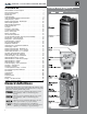

Part number 550-100-440/0122
10
(continued)
All piping methods shown in this manual use primary/
secondary connection to the boiler loop. ese designs
ensure proper ow through the Ultra boiler, for the most
ecient and reliable operation of the boiler and the heat-
ing system. For other piping methods, consult your local
WM Technologies representative or see separate Ultra
boiler piping guides.
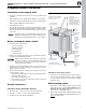
e boiler circulator (Taco 007 for Ultra-80 and -105; Taco 0014 for
Ultra-155, -230, and -299; Taco 0013 for Ultra-399) is shipped loose.
Locate it in the return piping, as shown in the appropriate piping
diagram in this manual.
DO NOT use the boiler circulator in any location other
than the ones shown in this manual. e boiler circula-
tor is selected to ensure adequate ow through the Ultra
boiler.
Install the boiler circulator only on the boiler return pip-
ing. is ensures the pressure drop through the boiler
will not cause low pressure in the circulator intake.
Failure to comply could result in unreliable performance
and nuisance shutdowns from insucient ow.
Size circulators based on the ow rate required to achieve the tem-
perature change needed. You can closely estimate temperature rise (or
drop) through a circuit by using the following formula, where TD is
temperature rise (or drop), FLOW is ow rate (in gpm), and BTUH is
the heat load for the circuit:
FLOW =
BTUH
—–—–—–—–
TD x 500
Examples:
Consider a system loop for a system with total heating load equal to
210,000 Btuh. e desired temperature drop through the system piping
is 20°F. en the required ow rate is:
FLOW =
210,000
—–—–—–—–
20 x 500
= 21 gpm
SIMPLIFIED: For 20° temperature drop, FLOW = MBH / 10.
Circulator head requirement
e circulator must be capable of delivering the required ow against
the head loss that will occur in the piping. Determine the pipe size
needed and the resultant head loss using accepted engineering meth-
ods. e simplied pipe sizing here is limited to residential systems,
and does not include systems with fan coil units or radiant tubing.
e following simplied method for pipe and circulator
sizing must be limited to residential applications using
baseboard (nned or cast iron), cast iron radiators or
convectors. DO NOT apply for radiant heating, fan coil
units or commercial installations.
1. Install the boiler and piping using the recommended
piping layouts beginning on page12 and in the AD-
VANCED section of this manual.
2. Size the piping and components for each circuit in the
space heating system using Figure3.
listed, the head loss in all piping will be 0.04 feet
per foot of pipe.
a. Determine the heating load (Btuh) for each circuit.
b. Calculate the ow rate for each circuit using its load.
To use a 20°F temperature drop, just divide the
MBH (1,000’s of Btuh) by 10.
Example — Flow for 20°F temp drop with 35,000 Btuh:
FLOW = 35MBH / 10 = 3.5 gpm
c. Find the pipe size in Figure3 that has a max ow rate just
larger than that required for the circuit.
d. Find the total equivalent length (TEL) of the circuit.
TEL accounts for losses through ttings and valves by
using the equivalent length of pipe that would cause the
same head loss. Add these numbers to the measured length
of the circuit to nd TEL in feet.
TEL is usually close to 1.5 times the length of
the circuit for residential baseboard, radiator or
convector applications.
e. Measure the length of each circuit from the circulator
outlet back to its inlet. en multiply this length times
1.5 to get the approximate TEL of the circuit.
f. Find the head loss for each circuit:
TEL = 1.5 X Circuit Length
(feet)
HEAD = TEL X 0.04
(feet water column)
g. NOTE: Size system header piping for the total ow of all
connected zones.
3. Example:
a. For a circuit with heating load = 45,000 Btuh (= 45 MBH).
Measured length of circuit is 88 feet.
b. Flow = 45 MBH / 10 = 4.5 gpm.
c. TEL = 1.5 x 88 feet = 132 feet.
d. From Figure3, select 1" pipe (max ow = 7.1 gpm).
e. Head loss = TEL x 0.04 = 132 x 0.04 = 5.28 feet.
f. Select a circulator that can deliver at least 4.5gpm at a
head of 5.28feet. (Read the NOTICE below.)
To use this method, limit the ow through
¾" nned-tube baseboard to 3.9 gpm, or use
1" baseboard and limit ow to 7.1 gpm. If the
total load of the circuit requires more ow,
split the circuit into two or more.
Also see Figure9,page15 for quick-selection
information for applications using Taco 007
circulators or equivalent for zone piping.
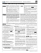
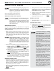
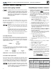
Figure 3
Flow rates for 0.04 feet head loss per foot of
pipe
(140°F water)
Pipe size
(inches)
MAX Flow rate (GPM)
@ 0.04 feet per foot
Pipe size
(inches)
MAX Flow rate (GPM)
@ 0.04 feet per foot
¾ 3.9 2 45
1 7.1 2½ 75
1¼ 16 3 140
1½ 24 4 290