
Ultra Boiler Manual

Part number 550-100-440/0122
5
BASIC INSTALLATION
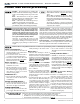
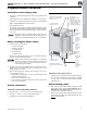
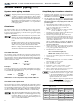
Figure 1 Clearances required
y Local, state, provincial, and national codes, laws, regulations and
ordinances.
y National Fuel Gas Code, ANSI Z223.1 /NFPA 54 – latest edition.
y Standard for Controls and Safety Devices for Automatically Fired
Boilers, ANSI/ASME CSD-1, when required.
y National Electrical Code.
y For Canada only: Natural Gas and Propane Installation Natural
Gas and Propane Installation
CAN/CSA
B149.1 or B149.2 Instal-
lation Code, CSA C22.1 Canadian Electrical Code Part 1 and any
local codes.
e Ultra boiler gas manifold and controls met safe
lighting and other performance criteria when boiler un-
derwent tests specied in ANSI Z21.13 — latest edition.
1. Check for nearby connection to:
• System water piping
• Venting connections
• Gas supply piping
• Electrical power
• Condensate drain
2. Check area around boiler. Remove any combustible materials,
gasoline and other ammable liquids.
Failure to keep boiler area clear and free of combustible
materials, gasoline and other ammable liquids and
vapors can result in severe personal injury, death or
substantial property damage.
3. e Ultra boiler must be installed so that gas control system com-
ponents are protected from dripping or spraying water or rain
during operation or service.
4. If new boiler will replace existing boiler, check for and correct
system problems, such as:
• System leaks causing oxygen corrosion or heat exchanger cracks
from hard water deposits.
• Incorrectly-sized expansion tank.
• Lack of freeze protection in boiler water causing system and
boiler to freeze and leak.
Clearances from combustible materials
1. Hot water pipes — at least ½” from combustible materials.
2. Vent pipe — at least
3/16” from combustible materials.
3. See Figure1 for other clearance minimums.
Clearances for service access
1. See Figure1 for recommended service clearances. If you
do not provide minimum clearances shown, it might
not be possible to service the boiler without removing
it from the space.
1. Ultra boilers can be wall mounted (using special wall
mount kit) or oor mounted. No clearance is re-
quired at the rear of the unit
, either for service or
for clearance to combustible surfaces.
2. Boilers can be wall mounted ONLY if using the optional
wall-mount kit available from WM Technologies. See
page50 for instructions.
12" maximum above
floor of enclosure
12" maximum below
ceiling of enclosure
U3002
Air/ventilation openings when
required — see “Provide air
openings to room”
TOP:
Service —
12" min
Combustible
surfaces —
½" min
Right SIDE:
Service or
combustible
surfaces —
3" min
Left SIDE:
Service —
3" min
Combustible
surfaces —
½" min
BOTTOM:
Service —
0" min
Combustible
surfaces —
0" min
FLUE PIPE:
Combustible surfaces —
3/16” min —
Opening in combustible
wall, floor, ceiling or roof
3/8" larger than flue pipe
diameter, fitted with
galvanized steel thimble.
Combustible
surfaces —
½" min
FRONT:
Service —
24" min
Air/ventilation openings
(see instructions in this manual)