
Ultra Boiler Manual

Part number 550-100-440/0122
9
BASIC INSTALLATION
Use two wrenches when tightening water piping at boiler,
using one of the wrenches to prevent the boiler interior
piping from turning. Failure to support the boiler piping
connections to prevent them from turning could cause
damage to boiler components.
Additional controls, when required
e U-Control module uses temperature sensors to
provide both high limit protection and modulating tem-
perature control. e U-Control module also provides
low water protection by sensing the temperature of the
heat exchanger. Some codes/jurisdictions may require
additional external controls for high limit and/or low
water cuto protection.
Additional limit controls
Following standard industry practices, if installation is to comply with
ASME or Canadian requirements, an additional high temperature limit
may be needed. Consult local requirements for other codes/standards
to determine if needed.
1. Install a manual reset high temperature limit constructed to prevent
a temperature setting above 200°F in system supply piping between
boiler and isolation valve. (Note that the U-Control module op-
erating limit function shuts the boiler down at 195°F, or lower if
set to a lower value.)
Multi-temperature systems — If the heating system
includes circuits that require lower temperature water
(radiant slab circuits, for example) as well as higher
temperature circuits, it is recommended to protect low-
temperature circuits with limit controls that are wired to
a U-Control external limit circuit (P13 terminals1 and2
for manual reset, or P13 terminals3 and4 for automatic
reset).
2. See instructions beginning on page30 for wiring information.
a. Manual reset operation: If external limit controls are to cause
manual reset of the U-Control module, connect series-wired
isolated contacts to P13 terminals 1 and 2 (see page30 for wir-
ing information).
b. Automatic reset operation: If external limit controls are to
cause
automatic reset of the U-Control module, connect
series-wired isolated contacts to P13 terminals 3 and 4 (see
page30 for wiring information).
c. If using a manual reset limit control or wiring in the manual
reset circuit, set U-Control boiler limit at least 20°F less than
the external manual reset limit (i.e., set U-Control no higher
than 180°F for a 200°F external limit, for example).
1. A low water cuto device is recommended when the boiler is in-
stalled above piping level, and may be required by certain state or
local codes or insurance companies. Consult local requirements to
determine. See the NOTICE above regarding the inherent protec-
tion provided by the U-Control module.
2. e U-Control’s integral protection is accepted in many jurisdic-
tions as meeting the requirement for low water protection. See
page95 for details.
3. When required, use a low water cuto designed for water
installations. Electrode probe-type is recommended. See
Replacement parts section at the end of this manual for
the Weil-McLain low water cut-o kit.
4. Purchase low water cuto and install in a tee in the sup-
ply piping above boiler.
5. See eld wiring instructions beginning on page30 for
wiring additional limit controls.
1. Use backow check valve in cold water supply as re-
quired by local codes.
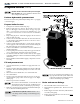
1. Install relief valve in ¾” street elbow piped from boiler
supply piping tee (Figure2,page8). Pipe the relief valve
only as shown, in the location shown.
2. Connect discharge piping to safe disposal location, fol-
lowing guidelines in the
WARNING below.
To avoid water damage or scalding
due to relief valve operation, as per
local or state codes
:
Discharge line must be connected to relief
valve outlet and run to a safe place of
disposal. Terminate the discharge line in
a manner that will prevent possibility of
severe burns or property damage should
the valve discharge.
Discharge line must be as short as pos-
sible and be the same size as the valve
discharge connection throughout its
entire length.
Discharge line must pitch downward from
the valve and terminate at least 6” above
the oor drain where any discharge will
be clearly visible.
e discharge line shall terminate plain,
not threaded, with a material serviceable
for temperatures of 375 °F or greater.
Do not pipe the discharge to any place
where freezing could occur.
No shuto valve shall be installed be-
tween the relief valve and boiler, or in the
discharge line. Do not plug or place any
obstruction in the discharge line.
Test the operation of the valve aer ll-
ing and pressurizing system by liing
the lever. Make sure the valve discharges
freely. If the valve fails to operate cor-
rectly, replace it with a new relief valve.
Failure to comply with the above guide-
lines could result in failure of the relief
valve to operate, resulting in possibility
of severe personal injury, death or sub-
stantial property damage.