® Gas-Fired Water Boilers Boiler Manual • Installation • Maintenance • Startup • Parts This manual must only be used by a qualified heating installer/service technician. BEFORE installing, read all instructions in this manual and all other information shipped with the boiler. Perform steps in the order given. Failure to comply could result in severe personal injury, death or substantial property damage.
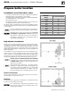
GV90+ gas-fired water boiler — Boiler Manual How it works . . . 1 Integrated boiler control The integrated boiler control (IBC) responds to signals from the room thermostat, air pressure switch, inlet water sensor and boiler limit circuit to operate the circulators, gas valve, igniter and blower. When a room thermostat calls for heat, the IBC starts the system circulator and blower. The IBC runs the blower to purge the boiler flue passages, then turns on the igniter and lets it warm up.
GV90+ gas-fired water boiler — Boiler Manual GV90+ Water Boiler Part number 550-142-054/0411 3
GV90+ gas-fired water boiler — Boiler Manual Contents How it works . . . . . . . . . . . . . 2 DIRECT VENT — Sidewall with W-M vent/air plate . . . . . . . . . . . 37 GV90+ Water Boiler . . . . . . . . 3 Please read before proceeding . . 5 Prepare boiler location . . . . . . . 6 Installations must follow these codes: . . . 6 High altitude installations . . . . . . . . . 6 Residential garage installation . . . . . . .
GV90+ gas-fired water boiler — Boiler Manual Please read before proceeding Failure to adhere to the guidelines on this page can result in severe personal injury, death or substantial property damage. Hazard definitions The following defined terms are used throughout this manual to bring attention to the presence of hazards of various risk levels or to important information concerning the life of the product.
GV90+ gas-fired water boiler — Boiler Manual Prepare boiler location Installations must follow these codes: • • • Local, state, provincial, national codes, laws, regulations and ordinances. National Fuel Gas Code, ANSI Z223.1- latest edition. Standard for Controls and Safety Devices for Automatically Fired Boilers, ANSI/ASME CSD-1, when required. • National Electrical Code. • For Canada only: B149.1 or B149.2 Installation Code and CSA C22.1 Canadian Electrical Code Part 1 and any local codes.
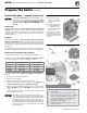
GV90+ gas-fired water boiler — Boiler Manual Prepare boiler location (continued) Foundation Figure 4 Provide a solid brick or concrete foundation pad if any of the following is possible: • When the floor can become flooded. • When the boiler mounting area is not level. • When a high-profile condensate pump is used, provide a foundation high enough that the GV90+ condensate connection is at least as high as the condensate pump inlet connection.
GV90+ gas-fired water boiler — Boiler Manual Prepare the boiler (continued) Check orifice plate — replace if necessary The correct orifice plate must be used. Failure to do so will result in severe personal injury, death or substantial property damage. The boiler is shipped with a natural gas orifice plate. It MUST BE CONVERTED to use propane. Natural gas: For natural gas installations, inspect the silver gas/air orifice plate marking. It must be the same as the boiler size.
GV90+ gas-fired water boiler — Boiler Manual Prepare the boiler (continued) Install condensate trap Figure 7 Install condensate trap 1. Before placing the boiler in position, install the condensate trap line, shown in Figure 7. Items shown are provided with the boiler. Step 1 Attach the flue drain hose (C) to the in-line flue drain nipple (B). Step 2 Slide a screw driver or pencil through the condensate drain nipple (G).
GV90+ gas-fired water boiler — Boiler Manual Prepare the boiler (continued) Install high altitude air pressure switch when required (only above 5,500 feet) Figure 8 Air pressure switch mounting 1. For installations at altitude more than 5,500 feet above sea level: a. A special high altitude air pressure switch is required. b. The gas valve outlet pressure setting must be checked, and adjusted if necessary, per the instructions on page 62.
GV90+ gas-fired water boiler — Boiler Manual Prepare the boiler (continued) Perform hydrostatic pressure test Figure 10 Piping connections for hydrostatic test Pressure test boiler before attaching water or gas piping (except as noted below) or electrical supply. Remove jacket top panel before proceeding. Use two wrenches when tightening water piping at boiler, using one of the wrenches to prevent the boiler interior piping from turning.
GV90+ gas-fired water boiler — Boiler Manual Install water piping Use two wrenches when tightening water piping at boiler, using one of the wrenches to prevent the boiler interior piping from turning. Failure to support the boiler piping connections to prevent them from turning could cause damage to boiler components. The cast iron heat exchanger return temperature must be kept at or above 140°F during all times of operation to prevent possibility of corrosion due to condensation.
GV90+ gas-fired water boiler — Boiler Manual Install water piping (continued) Figure 13 Relief valve installation guidelines To avoid water damage or scalding due to relief valve operation, as per local or state codes: Discharge line must be connected to relief valve outlet and run to a safe place of disposal. Terminate the discharge line in a manner that will prevent possibility of severe burns or property damage should the valve discharge.
GV90+ gas-fired water boiler — Boiler Manual Install water piping (continued) Figure 14 Piping to single-zone system using diaphragm- or bladder-type expansion tank. Boiler connections are 1” NPT (supply from 1” tee, return to 1” recuperator flange). Figure 15 Piping closed-type expansion tank Pipe diaphragm- or bladder-type expansion tanks to the bottom of the separator. Pipe closed-type (air in contact with water) tanks to the top of the air separator.
GV90+ gas-fired water boiler — Boiler Manual Install water piping (continued) System water piping methods Most piping methods shown in this manual use primary/secondary connection to the boiler loop. These designs ensure proper flow through the GV90+ boiler, for the most efficient and reliable operation of the boiler and the heating system. For other piping methods, consult your local WeilMcLain representative. Circulators Do not remove either of the GV90+ internal pumps for use elsewhere in the system.
GV90+ gas-fired water boiler — Boiler Manual Install water piping (continued) Baseboard system piping — CIRCULATOR zoning (primary/secondary) Figure 17 Baseboard system — circulator zoning Apply Figure 17 for circulator zoning on systems using baseboard heaters. The heaters can be any baseboard style, including finned tube or cast iron. Zoning with circulators — The GV90+ internal system circulator cannot be removed from the boiler for use as one of the zone circulators.
GV90+ gas-fired water boiler — Boiler Manual Install water piping (continued) Figure 18 Zone valve zoning — GV90+3, GV90+4 or GV90+5 (DO NOT apply to GV90+6) Legend 1 Isolation valves 4 Zone valve 2 Automatic air vent (with diaphragm-type expansion tank), or connect to tank fitting (closed-type expansion tank). 7 Hose bibb purge valve 8 Boiler pressure/temperature gauge 10 Differential pressure bypass valve 3 Diaphragm- or bladdertype expansion tank, if used.
GV90+ gas-fired water boiler — Boiler Manual Install water piping (continued) Radiator system piping Figure 20 Radiator system — zone-valve zoning Apply Figure 20 (zone-valve zoning) or Figure 21 (circulator zoning) to systems using standing cast iron radiators. This applies to gravity water systems and converted steam systems using columnar, tubular or recessed cast iron radiators.
GV90+ gas-fired water boiler — Boiler Manual Install water piping (continued) Single-zone radiant heating or heat pump Radiant heating systems and heat pump systems usually require system supply water temperatures below 140°F. But the boiler outlet water temperature will be at least 150°F to 160°F during most operating conditions. So the piping must include a method of reducing the supply water temperature to the system.
GV90+ gas-fired water boiler — Boiler Manual Install water piping (continued) Multi-zone radiant heating system Multi-zone systems require automatic regulation of the system supply temperature because of widely varying load conditions. Figure 23 (zone-valve zoning) and Figure 24 (circulator zoning) show suggested piping for these systems.
GV90+ gas-fired water boiler — Boiler Manual Install water piping (continued) Piping snow melt systems or combination snow melt/space heating systems Figure 25 Auto return temp regulation — circulator zoning Combination snow melt/space heating systems can have return water temperature below 60°F, and the return temperature will fluctuate. So these systems require automatic return water temperature as shown in Figure 25 (zone-valve zoning) or Figure 26 (circulator zoning).
GV90+ gas-fired water boiler — Boiler Manual Install water piping (continued) Water chiller systems Pipe the boiler and water chiller as shown in Figure 27. Install boiler, as shown, so chilled medium is piped in parallel with heating boiler. Use appropriate valves to prevent chilled medium from entering boiler. See Figure 27 for typical installation of balancing valve and check valve.
GV90+ gas-fired water boiler — Boiler Manual Multiple boiler installations Placing multiple boilers 1. Locate multiple boilers in boiler room according to: a. Figure 28 (side-to-side), or b. Figure 29 (back-to-back). 2. Provide the clearances indicated in the illustrations listed above to provide for access and servicing. If these recommended dimensions are not possible, provide at least the recommended service clearances given on page 6. Also follow local codes. 3.
GV90+ gas-fired water boiler — Boiler Manual Multiple boiler water piping Easy-Fit® piping installation 1. Main header and Easy-Fit® Manifold pipe sizing. a. New system — See page 15. b. Replacing boilers in an existing system — Without reducing size, connect system supply and return lines. Install tees or crosses for Easy-Fit® manifolds as shown in Figure 30 or Figure 31. Size manifolds to handle total connected boiler output as shown.
GV90+ gas-fired water boiler — Boiler Manual Multiple boiler water piping (continued) Figure 32 Piping schematic — typical for multiple GV90+ boilers, using Weil-McLain Easy-Fit manifolds Legend — Figure 32 1 Flow/check valve (each boiler) 2 Isolation valves (when used) 3 Cap 4 Easy-Fit® Manifold (supply) — layout and size per page 24 5 Easy-Fit® Manifold (return) — layout and size per page 24 6 Primary circulator 7 Expansion tank (diaphragm type) 8 System air eliminator 11 Check valve
GV90+ gas-fired water boiler — Boiler Manual Multiple boiler water piping (continued) Figure 33 Piping layout — typical for multiple GV90+ boilers, using Weil-McLain Easy-Fit manifolds (2-boiler system) Legend — Figure 33 1 2 3 4 5 6 7 8 9 16 26 Flow/check valve (each boiler) Isolation valves (when used) Caps Easy-Fit® Manifold (supply) — layout and size per page 24 Easy-Fit® Manifold (return) — layout and size per page 24 Primary circulator Expansion tank (diaphragm type) System air
GV90+ gas-fired water boiler — Boiler Manual Multiple boiler water piping (continued) Figure 34 Piping layout — typical for multiple GV90+ boilers, with DHW storage heaters (4-boiler system) Suggested DHW boiler-side pipe sizing (for max 0.
GV90+ gas-fired water boiler — Boiler Manual Multiple boiler water piping (continued) Figure 35 Piping layout — typical for multiple GV90+ boilers, using isolation exchanger Use isolation heat exchanger for: 1. Large volume systems with high mineral content in water. 2. Systems exposed to untreated quantities of makeup water. 3. Old systems severely contaminated with scale and rust buildup inside piping and heat distribution units. 4. Process applications. 5. Commercial service water applications. 6.
GV90+ gas-fired water boiler — Boiler Manual Venting & air — general GV90+ boilers must be vented and supplied with combustion and ventilation air using piping and methods described in this manual. Every boiler must have its own vent. DO NOT common vent with any other appliance. Inspect finished vent and air piping thoroughly to ensure all are airtight and comply with the instructions provided and with all requirements of applicable codes.
GV90+ gas-fired water boiler — Boiler Manual Venting & air — general (continued) Provide combustion air: Combustion air contamination: DIRECT VENT — The installation must provide combustion air piping. In addition, ventilation openings may be required. Ensure that the combustion air will not contain any of the contaminants in Figure 36. DIRECT EXHAUST — The installation must provide combustion air openings to the boiler space.
GV90+ gas-fired water boiler — Boiler Manual Venting & air — general (continued) Manifolded combustion air option for DIRECT VENT multiple boiler installations Figure 37 Combustion air manifold option (combined air inlet, but individual vents) — must comply with Figure 41, page 35 1. Multiple GV90+ boilers can use a common combustion air manifold. a. The combustion air inlet must be located in a sidewall (and the vents must terminate on the same side of the building). b.
GV90+ gas-fired water boiler — Boiler Manual Venting & air — general (cont.) Figure 39 GV90+ venting and air piping — OPTIONS and PIPING LIMITS Vent length affects boiler input — the boiler automatically derates to compensate for pressure loss through the vent. See the derate values given in Figure 109, page 101. The longer the vent, the more the input is reduced.
GV90+ gas-fired water boiler — Boiler Manual Venting & air — general (cont.
GV90+ gas-fired water boiler — Boiler Manual Commonwealth of Massachusetts installations Commonwealth of Massachusetts — When the boiler is installed within the Commonwealth of Massachusetts, the boiler must be installed by a licensed plumber or gas fitter. Read and comply with the instructions below.
GV90+ gas-fired water boiler — Boiler Manual Vent termination requirements Figure 41 The vent termination must be located to meet all requirements below (also applies to vertical vent terminations). For Canadian installations, defer to the requirements of CSA B149.1 or B149.2 Installation Code.
GV90+ gas-fired water boiler — Boiler Manual DIRECT VENT — Boiler room air openings Figure 42 Combustion and ventilation air openings for GV90+ Direct Vent installations The GV90+ boiler CANNOT be in the same space with other appliances if clearances around the GV90+ are less than the recommended service clearances shown in Figure 2, page 6. Air openings GV90+ boiler WITH other appliances in room The required air opening sizes below are FREE AREA, after reduction for louver obstruction.
GV90+ gas-fired water boiler — Boiler Manual DIRECT VENT — Sidewall with W-M vent/air plate Allowable vent/air pipe materials & lengths Figure 43 Installation — W-M sidewall vent/air plate Use only the vent materials and kits listed in Figure 40, page 33. Provide pipe adapters if specified. 1. Locate the termination such that the total air piping and vent piping from the boiler to the termination will not exceed the maximum length given in Figure 39, page 32. Determine termination location 1.
GV90+ gas-fired water boiler — Boiler Manual DIRECT VENT — Sidewall with W-M vent/air plate (continued) Install Weil-McLain vent/air cap Figure 44 Multiple terminations — Weil-McLain vent/ air plate — clearance from vent of one to air intake of the next The inside and outside cover plates are stamped to identify the exhaust (vent) and intake (air) openings. Make sure to orient the plates correctly. 1. Locate termination opening and avoid obstructions: a.
GV90+ gas-fired water boiler — Boiler Manual DIRECT VENT — Sidewall with separate pipes Allowable vent/air pipe materials & lengths Figure 47 Installation sequence — Separate pipes sidewall Use only the vent materials and kits listed in Figure 40, page 33. Provide pipe adapters if specified. 1. Locate the termination such that the total air piping and vent piping from the boiler to the termination will not exceed the maximum length given in Figure 39, page 32. Determine termination location 1.
GV90+ gas-fired water boiler — Boiler Manual DIRECT VENT — Sidewall with separate pipes (continued) For multiple boiler applications using the manifolded combustion air option, the vent can be terminated in an elbow as in Figure 47, page 39, or in a coupling or sidewall termination plate. The vents must be located following the restrictions in Figure 41, page 35 and Figure 48 Multiple separate pipes sidewall terminations Figure 38, page 31. Prepare wall penetrations 1. Air pipe penetration: a.
GV90+ gas-fired water boiler — Boiler Manual DIRECT VENT — Sidewall with 3” concentric Allowable vent/air pipe materials & lengths Figure 50 Installation sequence — Concentric horizontal 1. The 3” concentric termination kit must be purchased separately. Use only the vent materials and kits listed in Figure 40, page 33. Provide pipe adapters if specified. 2.
GV90+ gas-fired water boiler — Boiler Manual DIRECT VENT — Sidewall with 3” concentric (continued) Install termination — concentric pipes 1. Assemble the vent termination as described for concentric terminations, on page 47. If necessary, you can shorten the lengths of the inner and outer pipes for a shorter finished assembly. But you must ensure the pipes butt correctly at both ends.
GV90+ gas-fired water boiler — Boiler Manual DIRECT VENT — Vertical with separate pipes Allowable vent/air pipe materials & lengths Figure 53 Separate pipes vertical termination Use only the vent materials and kits listed in Figure 40, page 33. Provide pipe adapters if specified. 1. Locate the terminations such that the total air piping and vent piping from the boiler to the termination will not exceed the maximum length given in Figure 39, page 32. Determine termination location 1.
GV90+ gas-fired water boiler — Boiler Manual DIRECT VENT — Vertical with separate pipes (continued) 3. Space the air and vent holes to provide the minimum spacings shown in Figure 53, page 43. Figure 54 Terminations for multiple boilers 4. Follow all local codes for isolation of vent pipe when passing through floors, ceilings and roofs. 5. Provide flashing and sealing boots sized for the vent pipe and air pipe. Termination and fittings 1.
GV90+ gas-fired water boiler — Boiler Manual DIRECT VENT — Vertical with 3” concentric Allowable vent/air pipe materials & lengths Figure 55 Installation sequence — Concentric vertical 1. The 3” concentric termination kit must be purchased separately. Use only the vent materials and kits listed in Figure 40, page 33. Provide pipe adapters if specified. 2.
GV90+ gas-fired water boiler — Boiler Manual DIRECT VENT — Vertical with 3” concentric (continued) Mount concentric termination 1. Mount the termination as shown in Figure 57, page 46. 2. Support the concentric vent/air termination at the roof penetration as shown in Figure 57. • The supports/bracing used must support the termination assembly to prevent vertical slippage or sideways movement.
GV90+ gas-fired water boiler — Boiler Manual Concentric termination assembly Figure 58 3” PVC concentric termination assembly — DO NOT attach the rain cap until the termination has been inserted through the roof or wall and all supports have been installed. (sidewall or vertical) Assembling concentric termination 1. See Figure 58, page 47 for the details of the termination assembly. 2. Prepare the bird screen (purchased separately if not included with the kit). Cut the bird screen to size if required.
GV90+ gas-fired water boiler — Boiler Manual Vent and air piping and boiler connections DIRECT EXHAUST & DIRECT VENT Figure 59 Boiler vent and air connections Follow termination instructions 1. Read and follow all instructions for the termination type used before proceeding with this page. Installing vent and air piping 1. Work from the boiler to vent or air termination. Do not exceed the lengths given in the previous pages for either the air or vent piping. a.
GV90+ gas-fired water boiler — Boiler Manual DIRECT EXHAUST — Boiler room air openings Combustion air provision Special considerations The GV90+ boiler can use inside air if no contaminants are present in the boiler space. (If contaminants are likely to be present, install the boiler as a direct vent appliance, using the appropriate vent instructions in this manual.) Tight construction ANSI Z223.
GV90+ gas-fired water boiler — Boiler Manual DIRECT EXHAUST — Boiler room air openings (cont.) Figure 60 MINIMUM combustion air openings for direct exhaust applications — ALL OPENING SIZES ARE FREE AREA The GV90+ boiler CANNOT be in the same space with other appliances if clearances around the GV90+ are less than the recommended service clearances shown in Figure 2, page 6.
GV90+ gas-fired water boiler — Boiler Manual DIRECT EXHAUST — Sidewall DO NOT sidewall vent DIRECT EXHAUST APPLICATIONS at altitudes Figure 61 Installation sequence — Direct exhaust sidewall above 5,500 feet. Sidewall venting is only allowed for DIRECT VENT applications (ducted combustion air) at altitudes above 5,500 feet. Allowable vent/air pipe materials & lengths Use only the vent materials and kits listed in Figure 40, page 33. Provide pipe adapters if specified. 1.
GV90+ gas-fired water boiler — Boiler Manual DIRECT EXHAUST — Sidewall (continued) b. Provide metal cover plates (item 2, Figure 62). The outer plate MUST provide a stop to prevent the vent elbow from being pushed inward. (See NOTICE at right.) Hole diameters in the metal plates must be 35⁄8” for PVC pipe. For AL294C vent pipe and coupling (or elbow) — size hole large enough to clear vent pipe, but small enough to prevent the coupling (or elbow) from being pushed through.
GV90+ gas-fired water boiler — Boiler Manual DIRECT EXHAUST — Vertical Allowable vent/air pipe materials & lengths Figure 63 Installation sequence — Direct exhaust vertical Use only the vent materials and kits listed in Figure 40, page 33. Provide pipe adapters if specified. 1. Locate the termination such that the total air piping and vent piping from the boiler to the termination will not exceed the maximum length given in Figure 39, page 32. Determine termination location 1.
GV90+ gas-fired water boiler — Boiler Manual Gas piping Connecting gas supply piping Figure 64 Gas supply connection to GV90+ boiler gas manifold Do not connect gas supply to boiler or attempt to operate boiler unless the correct orifice plate has been verified or installed in accordance with page 8. Except where otherwise instructed in this manual, do not attempt to measure or adjust the outlet pressure setting of the gas valve.
GV90+ gas-fired water boiler — Boiler Manual Gas piping (continued) Natural Gas Figure 65 Pipe capacity for 0.60 specific gravity natural gas 1. Refer to Figure 65 for pipe length and diameter. Size gas supply piping for total flow to all connected appliances. For each GV90+ boiler, provide for the following gas flow (cfh = cubic feet per hour): Boiler model CFH natural gas GV90+3 70 GV90+4 140 GV90+5 105 GV90+6 175 2. Inlet pressure required at gas valve inlet: • maximum 13” w.c.
GV90+ gas-fired water boiler — Boiler Manual Wiring For your safety, turn off electrical power supply at service entrance panel before making any electrical connections to avoid possible electric shock hazard. Failure to do so can cause severe personal injury or death. Figure 66 Field wiring connections — service switch and thermostat (or end switch) provided by installer Installation must comply with: National Electrical Code and any other national, state, provincial or local codes or regulations.
GV90+ gas-fired water boiler — Boiler Manual Wiring (continued) Figure 68 Ladder wiring diagram Part number 550-142-054/0411 57
GV90+ gas-fired water boiler — Boiler Manual Wiring (continued) Figure 69 Schematic wiring diagram 58 Part number 550-142-054/0411
GV90+ gas-fired water boiler — Boiler Manual Start-up Eliminate all system leaks. Continual fresh makeup water will reduce boiler life. Minerals can build up in sections, reducing heat transfer, overheating cast iron, and causing section failure.
GV90+ gas-fired water boiler — Boiler Manual Start-up (continued) Check for gas leaks Before starting the boiler, and during initial operation, use a leak detector or smell near the floor and around the boiler for gas odorant or any unusual odor. Remove boiler front door and smell interior of boiler enclosure. Do not proceed with startup if there is any indication of a gas leak. Repair any leak at once.
GV90+ gas-fired water boiler — Boiler Manual Start-up (continued) 3. Inject all of the inhibitor supplied with the boiler. Allow time for the water to circulate and mix. Then check the inhibitor level. Add additional inhibitor if necessary. 5. Once the external thermostat circuit wiring is checked and corrected if necessary, reconnect the external thermostat circuit wires. Allow the boiler to cycle. Check/verify water chemistry Inspect/fill condensate system 1.
GV90+ gas-fired water boiler — Boiler Manual Start-up (continued) Final checks before starting boiler Figure 72 Check for igniter glow by looking into observation port on front of blower housing ❏❏ Review the boiler sequence of operation in Figure 75, page 65. ❏❏ Verify that the boiler and system are full of water and all system components are correctly set for operation. ❏❏ High altitude locations (over 5,500 feet) — verify that the high altitude pressure switch is installed per page 10.
GV90+ gas-fired water boiler — Boiler Manual Start-up (continued) 5. Position and zero manometer per manufacturer’s instructions. The manometer must have at least 6” of tubing above the fluid level or fluid may be drawn into the gas valve. Figure 73 Tools required for gas valve outlet pressure measurement If manometer fluid is drawn into gas valve body, gas valve must be replaced.
GV90+ gas-fired water boiler — Boiler Manual Start-up (continued) Final checklist Use the checklist following to ensure boiler is operating correctly. Have the following been completed? ❏❏ Is proper orifice plate installed? Refer to page 8 to check size and fuel type. ❏❏ Test additional field-installed controls — If boiler has a low water cutoff, additional high limit or other controls, test for operation as outlined by manufacturer.
GV90+ gas-fired water boiler — Boiler Manual Start-up (continued) Figure 75 Integrated boiler control (IBC) sequence of operation — status light indications STEPS Call for Heat? POWER TSTAT CIRC LIMIT PRESS SWITCH FLAME Timing (After Step 8, the cycle goes back to Step 1) 1. Standby • Waiting for call for heat NO — 2. Call for heat • Circulator on YES — 3. Limit circuit • Limit controls closed • Block switch contacts closed • Blower on YES — 4.
GV90+ gas-fired water boiler — Boiler Manual Start-up (continued) Figure 76 Operating instructions 66 Part number 550-142-054/0411
GV90+ gas-fired water boiler — Boiler Manual Annual start-up and general maintenance schedule Figure 77 Service and maintenance schedules Service technician Owner maintenance (see following pages for instructions) (see following pages for instructions) General: • Address reported problems, page 68. • Inspect boiler area, page 68. • Inspect boiler interior, page 68. • Check boiler area Daily • Check air openings • Check pressure gauge • Inspect condensate drain system, page 68.
GV90+ gas-fired water boiler — Boiler Manual Annual start-up Annual start-up only by qualified service technician The boiler should be inspected and started annually, at the beginning of the heating season, only by a qualified service technician. In addition, the maintenance and care of the boiler designated in Figure 77, page 67 and explained on the following pages must be performed to assure maximum boiler efficiency and reliability.
GV90+ gas-fired water boiler — Boiler Manual Annual start-up (continued) Inspect expansion tank 1. Expansion tanks provide space for water to move in and out as the heating system water expands due to temperature increase or contracts as the water cools. Tanks may be open, closed or diaphragm or bladder type. See page 13 of this manual for suggested location of expansion tanks and air eliminators. • Open-type — located above highest radiator or baseboard unit, usually in the attic or closet.
GV90+ gas-fired water boiler — Boiler Manual Annual start-up (continued) Inspect recuperator Figure 79 Blower motor 1. Follow the procedure on page 73 to inspect the recuperator and clean if necessary. Inspect temperature mixing system 1. Carefully check the temperature of the system return piping as it passes through the boiler jacket and on the return pipe inside the boiler jacket just before it enters the boiler sections.
GV90+ gas-fired water boiler — Boiler Manual Annual start-up (continued) Inspect boiler relief valve Figure 80 Relief valve 1. Inspect the relief valve (Figure 80) and lift the lever to verify flow as in the following warnings, excerpted from a relief valve manufacturer’s warning label. Before operating any relief valve, ensure that it is piped with its discharge in a safe area to avoid severe scald potential. Read page 12 before proceeding further.
GV90+ gas-fired water boiler — Boiler Manual Service & maintenance Cleaning boiler heating surfaces Figure 81 Blower housing removal procedure The service procedures in this manual must only be performed by a qualified boiler service technician. Failure to comply could result in severe personal injury, death or substantial property damage. The boiler contains ceramic fiber and fiberglass materials. Use care when handling these materials per instructions on page 107 of this manual.
GV90+ gas-fired water boiler — Boiler Manual Service & maintenance (continued) To clean the burner Figure 82 Recuperator access and cleaning The burner may contain ceramic fiber particles. Use care when handling these materials per instructions on page 107 of this manual. Failure to comply could result in severe personal injury. 1. Clean the burner ports with a soft brush. 2. Use compressed air to blow out any particulate if necessary. Use caution to avoid particulate being blown into the building.
GV90+ gas-fired water boiler — Boiler Manual Service & maintenance (continued) Removing/cleaning/re-installing the recuperator Figure 84 Recuperator flueway drain holes Disconnect the vent pipe from the recuperator 1. The vent pipe must be disconnected (at the in-line flue drain, item A in Figure 7, page 9). 2. If the vent piping can be moved enough, loosen the flue pipe clamp on the in-line flue drain. Then lift the flue pipe up and move aside slightly. 3.
GV90+ gas-fired water boiler — Boiler Manual Troubleshooting VERIFY PROPER OPERATION AFTER SERVICING. Label all wires prior to disconnection when servicing controls. Wiring errors can cause improper and dangerous operation. Figure 85 Connecting a manometer to check air pressure switch. DO NOT use this arrangement to check gas valve Never jumper (bypass) any device except for momentary testing as outlined in Troubleshooting charts.
GV90+ gas-fired water boiler — Boiler Manual Troubleshooting (continued) Igniter Figure 86 Igniter Wait several minutes until igniter cools down before attempting replacement. Failure to do so will cause severe personal injury. 1. Disconnect igniter (Figure 86) from igniter wiring harness and remove igniter before removing from blower assembly. 2. Replace igniter gasket if original gasket is frayed or damaged OR if room-temperature resistance across igniter is not between 40 and 95 ohms. 3.
GV90+ gas-fired water boiler — Boiler Manual Troubleshooting (continued) c. Immediately disconnect the return temperature sensor plug from the IBC. d. Measure the resistance of the sensor. Write down the result. e. Let the sensor cool to room temperature and measure the resistance again. Write down the result. f. Compare the sensor resistances at both temperatures to the closest temperatures in Figure 91. g. If the measured values are within 10% of the values listed, the sensor is good.
GV90+ gas-fired water boiler — Boiler Manual Troubleshooting (continued) Figure 93 IBC harness plug receptacle and indicator light locations 78 Part number 550-142-054/0411
GV90+ gas-fired water boiler — Boiler Manual Troubleshooting (continued) Figure 94 Common causes and possible corrections, part 1 Symptom Common Causes Possible Corrections Rapid cycling — boiler turns on and off frequently Thermostat installed where drafts or heat affect reading Locate thermostat on inner wall away from heat sources or cool drafts. Heat anticipator in thermostat adjusted incorrectly Adjust thermostat per manufacturer’s instructions.
GV90+ gas-fired water boiler — Boiler Manual Troubleshooting (continued) Figure 95 Common causes and possible corrections, part 2 Symptom Common Causes Possible Corrections Popping or percolating noise heard in boiler Mineral deposits in sections due to constant use of makeup water Call qualified service technician to delime boiler, if necessary. In some cases, deposits will be too heavy to remove with de-liming procedures.
GV90+ gas-fired water boiler — Boiler Manual Troubleshooting (continued) Troubleshooting POWER light status CHART 1 Electrical shock hazard — Wherever you see TURN OFF POWER, follow the instructions. Failure to follow instructions could result in severe personal injury, death or substantial property damage. Is POWER light off? No Yes • Make sure service switch or circuit breaker is on or fuses are good. • Remove 120 VAC IN plug (Figure 93, page 78, Item 1) on IBC.
GV90+ gas-fired water boiler — Boiler Manual Troubleshooting (continued) TSTAT CIRC & POWER lights flashing CHART 2 Electrical shock hazard — Wherever you see TURN OFF POWER, follow the instructions. Failure to follow instructions could result in severe personal injury, death or substantial property damage. Is return water temperature sensor clamped securely to the return pipe in the boiler? Yes • Attach sensor to pipe with clamp provided.
GV90+ gas-fired water boiler — Boiler Manual Troubleshooting (continued) LIMIT & POWER lights flashing CHART 3 Electrical shock hazard — Wherever you see TURN OFF POWER, follow the instructions. Failure to follow instructions could result in severe personal injury, death or substantial property damage. • This is a LOCKOUT condition.
GV90+ gas-fired water boiler — Boiler Manual Troubleshooting (continued) PRESS SWITCH & POWER lights flashing CHART 4 Electrical shock hazard — Wherever you see TURN OFF POWER, follow the instructions. Failure to follow instructions could result in severe personal injury, death or substantial property damage. • Reset boiler control by turning off power at service switch or turning down thermostat for at least 45 seconds. • Thermostat should call for heat and appropriate zone valves open.
GV90+ gas-fired water boiler — Boiler Manual Troubleshooting (continued) FLAME & POWER lights flashing CHART 5 Electrical shock hazard — Wherever you see TURN OFF POWER, follow the instructions. Failure to follow instructions could result in severe personal injury, death or substantial property damage. Are manual main shutoff valve and gas valve turned on? No • Open manual gas valve.` • Restart boiler, following Operating instructions on boiler (see Figure 76, page 66).
GV90+ gas-fired water boiler — Boiler Manual Troubleshooting (continued) TSTAT CIRC light flashing and POWER light on steady CHART 6 Electrical shock hazard — Wherever you see TURN OFF POWER, follow the instructions. Failure to follow instructions could result in severe personal injury, death or substantial property damage. • This is NOT a lockout mode.
GV90+ gas-fired water boiler — Boiler Manual Troubleshooting (continued) LIMIT light flashing and POWER light on steady CHART 7 Electrical shock hazard — Wherever you see TURN OFF POWER, follow the instructions. Failure to follow instructions could result in severe personal injury, death or substantial property damage. • This is NOT a lockout mode. The IBC should only be signaling that the water temperature sensor is either shorted or there is an open circuit across the sensor terminals.
GV90+ gas-fired water boiler — Boiler Manual Troubleshooting (continued) Insufficient heat or no heat to system (POWER light on steady) CHART 8 Electrical shock hazard — Wherever you see TURN OFF POWER, follow the instructions. Failure to follow instructions could result in severe personal injury, death or substantial property damage. • Has it been at least 5 minutes since setting thermostat to call for heat? If not, wait 5 minutes.
GV90+ gas-fired water boiler — Boiler Manual Replacement parts Figure 96 Miscellaneous parts Description Model Weil-McLain part number Vent Termination Kit for 3" PVC All 383-500-397 Vent Termination Kit for 3" Stainless Steel All 382-200-430 Vent Termination Bird Screen 3" PVC (1 pc) All 383-500-105 3" PVC Concentric Vent Kit All 383-500-350 Adapter 3-inch AL29-4C Vent Starter, FasNSeal All 560-907-717 Adapter 3-inch AL29-4C Vent Starter, Z-Vent All 560-907-723 Adapter 3-inch AL29-4
GV90+ gas-fired water boiler — Boiler Manual Replacement parts (continued) Figure 97 Section assembly Item number Model Weil-McLain part number 1 Block assembly, includes: Front section, intermediate section, back section, square cut seals — 2”, silicone sealant, tie rods, tie rod nuts, tie rod washers, blower flange gasket, igniter, igniter gasket, screws, lock washers, studs, nuts 3 4 5 6 322-200-304 322-200-305 322-200-306 322-200-307 2 Front section replacement kit, includes front section, sq
GV90+ gas-fired water boiler — Boiler Manual Replacement parts (continued) Figure 98 Section assembly Part number 550-142-054/0411 91
GV90+ gas-fired water boiler — Boiler Manual Replacement parts (continued) Figure 99 Jacket assembly Item number 92 Description Model Weil-McLain part number 1 Jacket panel, top 3&4 5&6 382-200-700 382-200-701 2 Jacket panel, front All 382-200-702 3 Jacket panel, left side, front 3&4 5&6 382-200-703 382-200-704 4 Jacket panel, left side, rear 3&4 5&6 382-200-705 382-200-706 5 Jacket panel, right side 3&4 5&6 382-200-724 382-200-725 6 Jacket panel, rear All 382-200-726 7 Jack
GV90+ gas-fired water boiler — Boiler Manual Replacement parts (continued) Figure 100 Jacket assembly Part number 550-142-054/0411 93
GV90+ gas-fired water boiler — Boiler Manual Replacement parts (continued) Figure 101 Blower assembly Item number Description 1 Burner replacement kit, includes burner, blower flange gasket, igniter, igniter screws, igniter washers, igniter gasket 2 3 — 4 Blower flange gasket Air pressure switch (0 to 5,500 feet elevation) Air pressure switch (5,500 to 10,000 feet elevation) Blower motor replacement kit, includes blower motor, motor mounting grommets, screws, lock nuts and 9" Allen wrench Blower ho
GV90+ gas-fired water boiler — Boiler Manual Replacement parts (continued) Figure 102 Blower assembly Part number 550-142-054/0411 95
GV90+ gas-fired water boiler — Boiler Manual Replacement parts (continued) Figure 103 Trim assembly Item number 96 Description Weil-McLain part number 1 System circulator, Taco 007 511-405-113 2 Bypass circulator, Taco 007 511-405-113 3 Circulator gasket, Taco 110-339 590-317-543 4 Manifold, casting/circulator kit, includes water manifold, circulator gasket (Taco 110-339) (2), square cut seal (manifold to casting) 382-200-720 5 Return manifold, recuperator/circulator kit, includes wate
GV90+ gas-fired water boiler — Boiler Manual Replacement parts (continued) Figure 104 Trim assembly Part number 550-142-054/0411 97
GV90+ gas-fired water boiler — Boiler Manual Replacement parts (continued) Figure 105 Interior panel Item number 98 Description Weil-McLain part number 1 Interior panel see Figure 99, page 92, item 8 2 Integrated boiler control assembly, includes IBC and screws 382-200-448 3 Transformer 511-842-370 4 Air pressure switch 5 Wiring harness, IBC to junction box (not shown) 591-391-963 6 Wiring harness, IBC to hot surface ignitor (not shown) 591-391-819 7 Wiring harness, IBC to system
GV90+ gas-fired water boiler — Boiler Manual Replacement parts (continued) Figure 106 Interior panel Part number 550-142-054/0411 99
GV90+ gas-fired water boiler — Boiler Manual Dimensions and ratings Figure 107 Dimension drawing (see Figure 108, page 101 for dimensional table) Item number 100 Description 1 1” NPT Supply 2 1” NPT Return 3 Combination pressure-temperature gauge, 2 ½” short shank 4 ¾” NPT Relief valve outlet 5 Plug dome, 2” black 6 Junction box 7 Inlet air fitting, 3" PVC 8 Flue outlet, 3" PVC 9 ½” Condensate drain 10 ½” NPT Gas supply connection (provided by others) 11 Drip leg (provided by o
GV90+ gas-fired water boiler — Boiler Manual Dimensions and ratings (continued) Figure 108 Boiler dimensional and physical data (see Figure 107, page 100) Boiler model Supply Return Length L Gas connection size (Note 1) Electrical service required Boiler water content Approx. shipping weight (includes the internal circulators) (inches NPT male) (inches NPT female) (inches) (inches NPT female) (amperes) (gallons) (pounds) GV90+3 1 1 30¾ ½ 15 3.8 313 GV90+4 1 1 30¾ ½ 15 4.
GV90+ gas-fired water boiler — Boiler Manual Dimensions and ratings (continued) Figure 110 Multiple GV90+ boilers — ratings and engineering data — maintain the clearances shown on pages 6 and 7 — see Figure 28, page 23 and Figure 29, page 23 for layout options Boilers in system Model GV90+ 3 4 5 6 2 2 2 2 3 3 3 3 4 4 4 4 5 5 5 5 6 6 6 6 7 7 7 7 8 8 8 8 Total CSA input DOE Heating capacity Boiler H.P.
GV90+ gas-fired water boiler — Boiler Manual Dimensions and ratings (continued) Figure 111 Engineering data — see page 101 for additional technical information Water flow rate per boiler Boiler Model Vent/air pipe size — Provide a separate vent for each boiler GPM @ 20°F rise GPM @ 40°F rise Note 1 GV90+3 6.5 3.3 3” GV90+4 9.7 4.9 3” GV90+5 13.0 6.5 3” GV90+6 16.1 8.1 3” Note 1 All GV90+ installations require a separate vent pipe and termination for each boiler.
GV90+ gas-fired water boiler — Boiler Manual NOTES 104 Part number 550-142-054/0411
GV90+ gas-fired water boiler — Boiler Manual NOTES (continued) Part number 550-142-054/0411 105
GV90+ gas-fired water boiler — Boiler Manual NOTES 106 Part number 550-142-054/0411
GV90+ gas-fired water boiler — Boiler Manual Handling ceramic fiber and fiberglass materials HANDLING CERAMIC FIBER MATERIALS REMOVAL OR INSTALLATION OF FIBERGLASS WOOL Ceramic fibers can be converted to cristobalite in very high temperature applications. The International Agency for Research on Cancer (IARC) has concluded, “Crystalline silica inhaled in the form of quartz or cristobalite from occupational sources is carcinogenic to humans (Group 1).
GV90+ gas-fired water boiler — Boiler Manual Installation and service certificate Boiler model __________________ Measured Btuh input ____________ Installer ________________________ (company) _______________________________ (installer’s signature) 108 Series __________ CP number ___________ Date installed _______________ Installation instructions have been followed. Check-out sequence has been performed. Above information is certified to be correct.