
Instruction manual

Part number 550-142-054/0411
GV90+ gas-fired water boiler — Boiler Manual
76
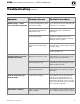
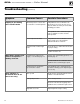
Troubleshooting (continued)
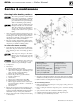
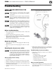
Figure 86 Igniter
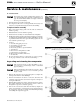
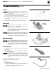
Figure 87 Gas valve
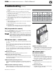
Figure 88 Blower housing
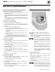
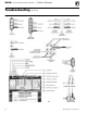
Figure 89 Thermal fuse
Figure 90 Return temperature sensor
Igniter
Wait several minutes until igniter cools down before at-
tempting replacement. Failure to do so will cause severe
personal injury.
1. Disconnect igniter (Figure 86) from igniter wiring harness and
remove igniter before removing from blower assembly.
2. Replace igniter gasket if original gasket is frayed or damaged OR
if room-temperature resistance across igniter is not between 40
and 95 ohms.
3. Igniter is fragile — handle with care. Do not touch igniter surface
with bare hands. Body oils can cause failure of the carbide.
Gas Valve
The gas valve (Figure 87) operates with a negative pres-
sure at the outlet — approximately –0.2” w.c. — DO
NOT set gas pressure higher than this.
Follow instructions in this manual carefully if testing
gas valve outlet pressure. Failure to comply can result in
severe personal injury or death.
The gas valve outlet is bolted to the gas line adapter and
sealed with an o-ring. When replacing valve, replace only
with valve listed in this manual for use with the GV90+
boiler. Failure to comply could result in severe personal
injury, death or substantial property damage.
Blower Housing
Do not disassemble blower housing (Figure 88). A
fire or explosion causing severe personal injury, death or
substantial property damage can result. If you suspect a
problem, replace blower housing. Follow instructions on
page 72 for blower housing removal and replacement.
Thermal fuse
1. The thermal fuse (Figure 89) protects vent pipe from excess flue
temperatures.
2. If the thermal fuse opens, it must be replaced. See page 94 for
replacement information.
If the thermal fuse opens, investigate the cause before
replacing switch and starting the boiler. DO NOT attempt
to jumper the switch. Failure to comply could result in
severe personal injury, death or substantial property
damage.
Return temperature sensor
1. See Figure 90.
2. Resistance check method:
a. With the boiler operating, use a contact thermometer to
measure the temperature of the return pipe next to the return
temperature sensor. Make a note of the temperature.
b. Turn the boiler ON/OFF switch off.