Installation & Operating Manual Single stage operation oil burners RETROFIT APPLICATIONS ONLY If this burner is being installed in a packaged unit (ie. burner comes with a boiler or furnace), follow the installation and set-up instructions supplied with the heating unit, as settings may differ from those shown in this manual. - The following pages contain information, descriptions and diagrams for the proper installation and wiring of the burner. Please read carefully before attempting final installation.
GB INSTALLLATION PRECAUTIONS AIR FOR COMBUSTION Do not install burner in room with insufficient air for combustion. Be sure there is an adequate air supply for combustion if the boiler/furnace room is enclosed. It may be necessary to create a window to permit sufficient air to enter the boiler/furnace room. The installer must follow local ordinances in this regard. CANADA It is suggested that the installer follow CSA standard B139. USA It is suggested that the installer follow NFPA manual #31.
GB TABLE OF CONTENTS PACKAGE CONTENTS LIST . . . . . . . . . . . . . . . . . . . . . . . . . . . . . . . . . . . . . . . . . . . . . . . . . . . . . . . . . . . . . . . . . . . . . . 1 SERIAL NUMBER IDENTIFICATION . . . . . . . . . . . . . . . . . . . . . . . . . . . . . . . . . . . . . . . . . . . . . . . . . . . . . . . . . . . . . . . . 1 TECHNICAL DATA . . . . . . . . . . . . . . . . . . . . . . . . . . . . . . . . . . . . . . . . . . . . . . . . . . . . . . . . . . . . . . . . . . . . . . . . . . . . .
GB PACKAGE CONTENTS LIST Your Riello 40 burner should include the following parts. Please check to make sure all parts are present before beginning the installation.
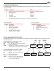
GB TECHNICAL DATA B SPECIFICATIONS No heavier than # 2 fuel oil 0.50 to 0.95 US GPH - 70,000 to 133,000 BTU/h 0.75 to 1.65 US GPH - 105,000 to 231,000 BTU/h 120V 60Hz (+ 10% - 15%) 155 Watts 175 Watts 3250 rpm Run Current 2.2 AMP 12.
GB INITIAL SET-UP A) Remove burner and air tube from cartons. Check parts list (inside cover) to ensure all parts are present. B) Remove burner cover by loosing the three screws securing it. Remove control box and air tube cover. C) Remove drawer assembly from air tube, insert nozzle and set Turbulator adjustment for specific input required, then set aside. D) Mount air tube to burner chassis.
GB A) Insert the two BOLTS (1) into the UNIVERSAL MOUNTING FLANGE (10) from the flat side, ensuring the bolt heads are flush with the flat surface. Secure in place using two special CHROME NUTS (2) provided. B) Position the MOUNTING GASKET (3) between the flat surface of the UNIVERSAL MOUNTING FLANGE (10) and the appliance. Line up the holes in the UNIVERSAL MOUNTING FLANGE with the STUDS (4) on the appliance mounting plate and securely bolt the UNIVERSAL MOUNTING FLANGE to the plate.
GB AMULET INSTALLATION INSTRUCTIONS Amulet shown in the flush mounted position (Required on some models) The amulets provided have been selected by Riello to protect the combustion tube from hot exhaust gases and flame. This protection may be needed in applications where the combustion tube opening in the combustion chamber refractory is larger than the tube outside diameter. The amulet has been sized to fit Riello Model 40 sizes F3 and F5 plus the Riello Model R35.
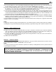
GB INTERNAL FACTORY WIRING RIELLO 40 F3 - F5 SERIES OIL BURNERS EQUIPPED WITH AN ELECTRONIC AIR SHUTTER INTERNAL FACTORY WIRING ELECTRONIC AIR SHUTTER ASSY.
GB APPLICATION FIELD WIRING WIRING DIAGRAM SHOWN BELOW FOR STANDARD RIELLO 530 SE/C PRIMARY CONTROL BOX. INSTALLATION NOTE: ELECTRONIC AIR SHUTTER REQUIRES A CONSTANT 120V POWER SUPPLY TO THE AUX TERMINAL, FAILURE TO PROVIDE THIS WILL RESULT IN NO BURNER OPERATION OR AIR SHUTTER WILL NOT CLOSE. AIR SHUTTER MOTOR 24V SWITCHING RELAY AIR SHUTTER MOTOR PLEASE NOTE: OPERATING LIMIT AND SAFETY LIMIT ARE TWO SEPARATE LIMITS.
GB NOZZLE PLACEMENT A) Determine the proper firing rate for the boiler or furnace units, considering the specific application, and then use the Burner Setup charts on page 12 to select the proper nozzle and pump pressure to obtain the required input from the burner. B) Remove the NOZZLE ADAPTER (2) from the DRAWER ASSEMBLY by loosening the SCREW (1). C) Insert the proper NOZZLE into the NOZZLE ADAPTER and tighten securely (Do not over tighten).
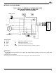
GB OIL LINE CONNECTIONS This burner is shipped with the oil pump set to operate on a single line system. To operate on a two-line system the by-pass plug must be installed. WARNING: Do not operate a single line system with the by-pass plug installed. Operating a single line system with the by-pass plug installed will result in damage to the pump shaft seal. NOTE: Pump pressure must be set at time of burner start-up. A pressure gauge is attached to the PRESSURE PORT (8) for pressure readings.
GB ATTENTION: do not exceed pipe lengths indicated in chart! D6008 H 2 LINE (LIFT) SYSTEM-PIPE LENGTHS H 3/8” OD 1/2” OD FT M FT M FT M 0.0 0.0 115 35 330 100 1.5 0.5 100 30 330 100 3.0 1.0 80 25 330 100 5.0 1.5 65 20 295 90 6.5 2.0 50 15 230 70 9.5 3.0 25 8 100 30 11 3.5 20 6 65 20 P H TWO LINE (LIFT SYSTEM) A) If a two-line system is required, install the By-pass plug provided. The by-pass plug is installed in the return port of the pump. A 2.
GB 7) Run the burner until the fuel pump has been purged of air, then tighten the bleeder valve and immediately shut down the burner. 8) Reinstall the air tube cover and nozzle line. 9) The burner can now be started normally. WARNING: Omitting steps 2 and 3 will result in a collection of unburned oil in the combustion chamber creating a hazardous situation upon burner startup. B) TWO LINE (LIFT SYSTEM) Turn off the main power source to the burner and remove the air tube cover.
GB BURNER ADJUSTMENT TABLE NON-RETROFIT APPLICATIONS If this burner is being installed in a packaged unit (i.e. Burner comes with a boiler or furnace), follow the installation and set-up instructions supplied with the heating appliance, as settings will differ from those shown in this manual. RIELLO BURNER SET UP SHEET Weil McLain Part No. 8000-5700 8000-5800 8000-5900 Riello Part No. Riello 40 Burner Model Series Boiler Input GPH Nozzle Delavan C8512519 F5 Factory F5 preset *1 UO3 UO3 0,8 1,0 .
EXPLODED SPARE PARTS LIST { 35 13
SPARE PARTS LIST No.
SPARE PARTS LIST No. 40 40 41 41 42 43 44 44 45 45 46 46 47 48 48 F5 DESCRIPTION CODE 3948876 3006968 3006977 3006966 3006965 3008627 3008629 3008633 3008634 3008630 3008631 3005869 3008623 3008626 C7001331 • • • • • • C7001335 • • • • • • • • • • • • VSBT COMBUSTION HEAD 3” F5 SBT WELDED 4.
GB 35 Pond Park Rd. Hingham, MA 02043 Phone: 781-749-8292 Toll Free: 800-992-7637 Fax: 781-740-2069 2165 Meadowpine Blvd. Mississauga,On L5H 3R2 Phone: 905-542-0303 Toll Free: 800-387-3898 Fax: 905-542-1525 BURNER START- UP FORM * Appliance: Burner S/N.
35 Pond Park Road Hingham, MA 02043 Phone 781-749-8292 Toll Free 800-992-7637 Fax 781-740-2069 www.riellousa.com 2165 Meadowpine Blvd Mississauga, ON L5N 6H6 Phone 905-542-0303 Toll Free 800-387-3898 Fax 905-542-1525 www.riellocanada.