
Single Stage Operation Oil Burners Installation & Operating Manual


3223
11
GB
7) Run the burner until the fuel pump has been purged of air, then tighten the bleeder valve and immediately
shut down the burner.
8) Reinstall the air tube cover and nozzle line.
9) The burner can now be started normally.
WARNING: Omitting steps 2 and 3 will result in a collection of unburned oil in the combustion chamber creating a haz-
ardous situation upon burner startup.
B) TWO LINE (LIFT SYSTEM)
Turn off the main power source to the burner and remove the air tube cover.
Shines a light source on the photocell (now visible where the air tube cover was removed), return power to the burner
and activate the burner. With the light source in place, the burner will operate in prepurge only. When the pump is suffi-
ciently purged, the hydraulic air shutter will open.
Once the burner is purged, turn off the power source and replace the air tube cover.
Return power to the burner. The burner is now ready to operate.
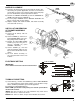
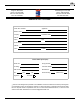
SETTING THE AIR ADJUSTMENT PLATE
The electronic air shutter assembly (1) is operated on a
120V 60Hz. motor, and the burner motor will not operate un-
til the air shutter is in its fully open position.
Set the air plate (4) setting according to OEM setup informa-
tion or by following the Retrofit settings listed in this manual.
To adjust the air plate (4) to the desired set point indicator
(2), loosen the center air shutter assembly screw (5) and
loosen the side air plate screw (3), move air plate (4) by us-
ing the air plate adjust arm. After adjustments are made
please retighten screws (3) & (5).
The final position of the air adjustment plate will vary on
each installation. Using proper combustion test instruments
to establish the proper setting of the air gate setting to
achieve safe and efficient results according the appliance
information or if not available.
NOTE: Variations in flue gas, smoke, CO
2
and temperature readings may be experienced when burner cover is put
in place. Therefore, the burner cover must be in place when making final combustion instrument readings, to ensure
proper test results are obtained.
ATTENTION:
It is important that the fuel line be completely sealed and free from air leaks or any internal blockages.
WARNING! WHEN THE BYPASS PLUG IS INSTALLED, A TWO-PIPE SYSTEM MUST BE USED OR FAILURE OF
THE PUMP SHAFT WILL OCCUR.
4
5
3
2
D7305
1