
Single Stage Operation Oil Burners Installation & Operating Manual


3223
12
GB
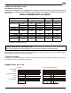
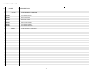
BURNER ADJUSTMENT TABLE
NON-RETROFIT APPLICATIONS
If this burner is being installed in a packaged unit (i.e. Burner comes with a boiler or furnace), follow the instal-
lation and set-up instructions supplied with the heating appliance, as settings will differ from those shown in
this manual.
Note: Any approved oil burner nozzle type, angle and manufacturer maybe used, as long as input is corresponding the
correct BTU/hr. or US gph input rating of the appliance.
COMBUSTION CHAMBER
Follow the instructions furnished by the boiler/furnace manufacturer. Size retrofit application according to the appropri-
ate installation codes (e.g. CSA B139 or NFPA #31).
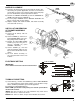
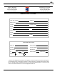
BURNER START-UP CYCLE
NOTE:
The above set up charts are a starting point only.
The burner and appliance must be properly set up using proper combustion testing equipment.
Normal Lock-out, due to light-failure
Thermostat
Motor
Ignition transformer
Valve
Flame
Lock-out lamp
~ 12s ~ 12s ~ 5s
D5229
8000-5800 8000-5900
C8512520 C8512521
Riello 40
Series
F5
F5 Factory
preset *1
F5 Factory
preset *1
F5 Factory
preset *1
Boiler UO3 UO3 UO4 UO5
Input GPH 0,8 1,0 1,2 1,4
Nozzle Delavan .65 X 70°B .85 X 60°B 1.00 X 70°B 1.10 X 70°B
Pump Pressure PSI 150 145 145 160
0134
2.75 2.8 2.9 2.9
Air tube length inches 8 8 8 8
Ait tube insertion inches 4 1/4" 4 1/4" 4 1/4" 4 1/4"
*1 Nozzle pre-installed at factory.
Burner Model
Turbolator Setting
Air Gate Setting
C8512519
Weil McLain Part No.
Riello Part No.
RIELLO BURNER SET UP SHEET
8000-5700