
Oil Burners Installation & Operating Manual


3398
8
GB
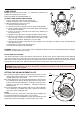
PUMP PURGE
NOTE: To protect the pump gears, it is advisable to lubricate the
pump prior to purging a lift system.
Apply oil through the VACUUM PORT (C).
A) SINGLE LINE (GRAVITY FEED SYSTEM)
I. Loosen the bleeder valve (A) until oil flows out.
Tighten the bleeder valve securely and startburner.
II. When bleeding the pump by pressure:
1) Loosen the bleeder valve (A).
2) Disconnect nozzle oil supply line at the pump nozzleport (B).
3) Attach a flexible plastic tube to the pump nozzle, port directing
the oil flow into a bucket.
4) Loosen the screw(s) securing the air tube cover, allowing it to
be removed freely.
5) Holding the air tube cover in its proper location start the burner.
6) When the solenoid valve is engaged approximately 10 seconds
after starting, remove the air tube cover and shine a light
source on the photocell, allowing it to see false light.
7) Run the burner until the fuel pump has been purged of air, then tighten the bleeder valve and immediately
shut down the burner.
8) Reinstall the air tube cover and nozzle line.
9) The burner can now be started normally.
WARNING: Omitting steps 2 and 3 will result in a collection of unburned oil in the combustion chamber creating a
hazardous situation upon burner startup.
B) TWO LINE (LIFT SYSTEM)
Turn off the main power source to the burner and remove the air tube cover. Shines a light source on the photocell
(now visible where the air tube cover was removed), return power to the burner and activate the burner. With the
light source in place, the burner will operate in prepurge only. Once the burner is purged, turn off the power source
and replace the air tube cover. Return power to the burner. The burner is now ready to operate.
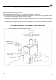
SETTING THE AIR ADJUSTMENT PLATE
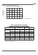
A) The initial air damper setting is made by turning screw (2) until
the top edge of the air damper (3) is aligned with the number ac-
cording to the burner setup chart.
B) Further adjustments can be made with the burner cover in place
by removing plastic plug on the top right hand side of the cover.
Turn the screw counter clockwise (+ indicator) to increase com-
bustion air, turn the screw clockwise (- indicator) to decrease
combustion air.
C) The final position of the air damper will vary on each installation.
Use instruments to establish the proper settings for maximum
CO
2
and a smoke reading of zero.
NOTE:
Variations in flue gas, smoke, CO
2
, and temperature readings may
be experienced when the burner cover is put in place.
Therefore, the burner cover must be in place when making the final
combustion instrument readings, to ensure proper test results.
ATTENTION: It is important that the fuel line be completely sealed and free from air leaks or any internal blockages.
WARNING! WHEN THE BYPASS PLUG IS INSTALLED, A TWO-PIPE SYSTEM MUST BE USED OR FAILURE OF
THE PUMP SHAFT WILL OCCUR.
D7527
C
A
B
2
1
3
D5141