
Operating instructions

15
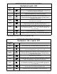
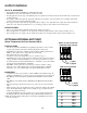
PURGE TIME DEFAULT is 0
Select button pressed 6 Times
• Many units must go through a purge cycle before they are brought on line and can begin generating heat or cooling.
• The Purge Time should be set to the time of the unit’s purge cycle.
• The Purge Time applies to every stage with ON/OFF units.
• The Purge Time applies only to the Lo stages of multiple stage units.
• When an ON/OFF stage, or a Lo stage, is turned on, the BCP-6/12 will begin counting down the Purge Time. When the Purge
Time has elapsed, then the BCP-6/12 will begin counting down the Reaction Time. Therefore, if the Purge Time applies to a
particular stage, the minimum run time of that stage is the Purge Time plus half a Reaction Time.
• The Purge Time can be set from 0 minutes (0.0) to 10 minutes (10.0).
LEAD STAGE
LEAD STAGE LIGHTS
• The row of green lights marked LEAD indicate which stage is currently the Lead Stage.
• The stage with the green light on is currently the Lead Stage.
• Only one stage can be the Lead Stage at any given time. The Lead Stage is always the first stage brought on when there is a call
for output.
LEAD STAGE SWITCH
• The LEAD STAGE switch controls the rotation of the stages.
• A unit can not be lead if any of its OFF/AUTO/ON switches is not set to AUTO. Any unit which has a one or more stages
switched ON or OFF is not considered as part of the rotation.
• Only the Lo stages of lo/hi boilers can be selected to be lead.
• If the LEAD STAGE switch is in the OFF position, whichever stage is presently the Lead Stage will remain the Lead Stage until
power is lost (then it will revert back to the first available stage).
• To change the current lead stage, press the LEAD STAGE switch to the INCREMENT position and then release it. The green
light indicating Lead Stage will increment to the next available stage.
• To automatically rotate the lead stage, switch the LEAD STAGE switch to the AUTO position (the different types of rotation are
described below).
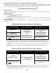
FIRST ON/LAST OFF ROTATION
• For this type of rotation, dip switch 5 must be in the OFF position.
• On power up, or any time the BCP-6/12 loses power, the Lead Stage will be the first possible lead stage (as described above).
• After the first 12 hours of power, the Lead Stage will change to the next possible stage.
• Subsequently, every 24 hours, the Lead Stage will change to the next possible stage.
• The Lead Stage will always be the first stage brought on when there is a call for output.
• As more output is needed, additional stages are added.
• When less output is needed, the additional stages are turned off in the reverse order of how they were added. For instance, if the
stages were added in the sequence 1, 2, and 3, then they will be turned off in the sequence 3, 2, and finally 1.
FIRST ON/FIRST OFF ROTATION
• For this type of rotation, dip switch 5 must be in the ON position.
• On power up, or any time the BCP-6/12 loses power, the Lead Stage will be the first possible stage (as described in Lead Stage
Switch).
• The Lead Stage will always be the first stage brought on when there is a call for output.
• As more output is needed, additional stages are added.
• When less output is needed, the Lead Stage will be the first stage turned off. The green light indicating lead stage will then
switch to the next available stage. For instance, if the stages were added in the sequence 1, 2, and 3, then they will be turned off
in the sequence 1, 2, and finally 3. The lead stage would now be 4 when more output is needed.