AHE Series 4 Direct Vent Wall-Mounted Boilers — Boiler Manual Contents Please read before proceeding .............................................................................. 3 1 Prepare boiler location ......................................................................................... 4-7 2 Venting ................................................................................................................ 8-13 3 Prepare boiler ...........................................................
AHE Series 4 Direct Vent Wall-Mounted Boilers — Boiler Manual Please read before proceeding Installer User Read all instructions before installing. Follow all instructions in proper order to prevent personal injury or death. Consider piping and installation when determining boiler location. Any claims for damage or shortage in shipment must be filed immediately against the transportation company by the consignee.
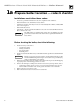
AHE Series 4 Direct Vent Wall-Mounted Boilers — Boiler Manual 1a Prepare boiler location — codes & checklist Installations must follow these codes: • • • • • Local, state, provincial and national codes, laws, regulations and ordinances. National Fuel Gas Code, ANSI Z223/1–latest edition. Standard for Controls and Safety Devices for Automatically Fired Boilers, ANSI/ASME CSD-1 when required. National Electrical Code. Canada only — B149.1 or B149.2 Installation Code, CSA C22.
AHE Series 4 Direct Vent Wall-Mounted Boilers — Boiler Manual 1b Prepare boiler location — clearances Provide the following clearances: 1. 2. Recommended minimum service clearances — See Table 1. Recommended clearances for enclosed cabinet, alcove or closet — See Table 1. Flooring Boiler must not be installed on or over carpeting. Do not install boiler on carpeting even if foundation is used. Fire can result, causing severe personal injury, death or substantial property damage.
AHE Series 4 Direct Vent Wall-Mounted Boilers — Boiler Manual 1c Prepare boiler location — vent system When removing boiler from existing common vent system: At the time of removal of an existing boiler, the following steps shall be followed with each appliance remaining connected to the common venting system placed in operation, while the other appliances remaining connected to the common venting system are not in operation. a. Seal any unused openings in the common venting system. b.
AHE Series 4 Direct Vent Wall-Mounted Boilers — Boiler Manual 1d Prepare boiler location — air openings Combustion air Combustion air must be ducted directly from outside to the AHE boiler air intake fitting. This method is defined as “direct vent” (also referred to as “sealed combustion”). Refer to Section 2, page 8, in this manual for venting instructions. Two options are available: side venting and back venting.
AHE Series 4 Direct Vent Wall-Mounted Boilers — Boiler Manual 2a Venting — vent/air intake pre-installation General information 1. 2. Installations must comply with all local, state and national codes including National Fuel Gas Code, ANSI Z223.1–latest edition. Canadian installations must comply with B149.1 or B149.2 Installation Codes. Two venting options are available for AHE boilers — side venting and back venting.
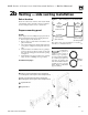
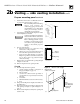
AHE Series 4 Direct Vent Wall-Mounted Boilers — Boiler Manual 2b Venting — side venting installation Select location Figure 1 Review all connection, clearance and vent/air intake considerations before selecting location. See Figure 1 for side venting clearance access to outside wall. Prepare mounting panel Inside Refer to Figure 3, below, and Figure 32, page 44. Choose right or left instructions based on venting direction. 1. Remove right (or left) knockouts. 2.
AHE Series 4 Direct Vent Wall-Mounted Boilers — Boiler Manual 2b Venting — side venting installation con’t Prepare mounting panel continued 6. Determine boiler location. See Manual Section 2a on page 8 and “Select location” on page 9. Before installing boiler and venting, inspect wall locations for obstructing piping and electrical supply. Failure to do so will result in severe personal injury, death or substantial property damage. 7.
AHE Series 4 Direct Vent Wall-Mounted Boilers — Boiler Manual 2b Venting — side venting installation con’t Prepare mounting panel continued Inside 15. Insert wall sleeve (see Figure 32, item 1, page 44) into outside wall plate assembly. 16. Measure tube lengths. See Figure 6 on page 10. 17. Cut tube lengths. Top tube will be longer than bottom tube. 18. Final location of boiler will be determined by proper slope to vent/air intake tubes.
AHE Series 4 Direct Vent Wall-Mounted Boilers — Boiler Manual 2c Venting — back venting installation Prepare mounting panel Inside 1. 2. 3. Inspect boiler wall location for obstructing piping and electrical supply prior to drilling and boiler installation. Failure to do so will cause severe personal injury, death or substantial property damage.
AHE Series 4 Direct Vent Wall-Mounted Boilers — Boiler Manual 2c Venting — back venting installation Prepare mounting panel continued Figure 9 con’t Back venting installation Inside 8. 9. 10. 11. 12. 13. 14. 15. 16. 17. Insert inside cover plate assembly into opening. Inside wall sleeve fits into outside wall sleeve. “Up” stamp must be up. Insert tube into top opening, until it stops. Mark length ½" longer than plate. Cut tube. Repeat step 9 for lower tube. Remove inside cover plate assembly.
AHE Series 4 Direct Vent Wall-Mounted Boilers — Boiler Manual 3 Prepare boiler — placement and setup Hang boiler on mounting panel 1. 2. 3. 4. 5. 6. 7. Remove crate top and wrapper. Leave bottom skid attached to boiler to aid hanging boiler. Cut bottom shipping strap located around boiler base. Do not cut upper strap. Place generous amount of silicone sealant around plenum box openings on mounting panel. Set gaskets (provided) in place. See Figure 11.
AHE Series 4 Direct Vent Wall-Mounted Boilers — Boiler Manual 4a Water piping — general information General piping information Expansion tank 1. 1. 2. 3. 4. 5. 6. Pipe as shown in Figure 12. Refer to I=B=R Installation and Piping Guides for additional recommendations. If system is to comply with ASME or Canadian requirements, an additional high temperature limit is needed. Install control in supply outlet piping close to the boiler. See page 23 for wiring.
AHE Series 4 Direct Vent Wall-Mounted Boilers — Boiler Manual 4a Water piping — general information Water treatment See WARNING on page 3 for important information regarding boiler water. For unusually hard water areas or low pH water conditions (below 7.0) consult local water treatment company. 1. 2. 3. 4. Freeze protection See WARNING on page 3 for important information regarding glycol hazard. Do not use ethylene glycol, automotive or undiluted antifreeze. Severe personal injury or death can result.
AHE Series 4 Direct Vent Wall-Mounted Boilers — Boiler Manual 4c Water piping — refrigeration systems Prevent chilled water from entering boiler Figure 14 Piping refrigeration systems Install boiler so that chilled medium is piped in parallel with the heating boiler. Use appropriate valves to prevent chilled medium from entering boiler. See Figure 14 for typical installation of balancing valve and check valve.
AHE Series 4 Direct Vent Wall-Mounted Boilers — Boiler Manual 5 Gas piping Natural gas piping Connecting gas piping to boiler 1. 1. 2. 2. 3. Refer to Table 4 for pipe length and diameter. Base on rated boiler input (divide by 1,000 to obtain cubic feet per hour). Table 4 is only for gas with specific gravity, 0.06, with a pressure drop through the gas piping of 0.03" w.c. For additional gas pipe sizing information, refer to ANSI Z223.1 (or B149.1 or B149.2 for Canadian installations).
AHE Series 4 Direct Vent Wall-Mounted Boilers — Boiler Manual 6 Field wiring For your safety, turn off electrical power supply at service entrance panel before making any electrical connections to avoid possible shock hazard. Failure to do so can cause severe personal injury or death. Wiring must be N.E.C. Class 1. Boiler must be electrically grounded as required by National Electrical Code ANSI/NFPA 70–latest edition.
AHE Series 4 Direct Vent Wall-Mounted Boilers — Boiler Manual 8a Start-up Final check before starting boiler Boiler water Review Manual Section 4, pages 15 through 17, regarding water piping, treatment, freeze protection and system pressure testing. Verify boiler is filled with water. Check for gas leaks Before starting the boiler and during initial operation, smell near the floor and around the boiler for gas odorant or any unusual odor.
AHE Series 4 Direct Vent Wall-Mounted Boilers — Boiler Manual 9 ❏ ❏ ❏ ❏ ❏ ❏ ❏ ❏ ❏ Checkout procedure Boiler and heat distribution units filled with water or antifreeze solution? Automatic air vent cap open two full turns during air purging procedure, then closed and opened one turn? Air purged from system? Air purged from gas piping? Piping checked for leaks? Followed operating instructions on boiler or in Manual Section 10c, pages 24-25, for proper start-up? Proper burner flame observed? Refer to “Che
AHE Series 4 Direct Vent Wall-Mounted Boilers — Boiler Manual 10a Operation — sequence Figure 17 shows the AHE boiler control module sequence of operation with status light indications. For more information, refer to “Troubleshooting” section beginning on page 32. Figure 17 Control module sequence of operation POWER Steps TSTAT CIRC Call for heat? LIMIT PRESS SWITCH FLAME Timing (Following step 8, cycle goes back to step 1.) 1.
Part number 550-141-887/0800 WIRE NUTS (note 8) SERVICE SWITCH Y Red W BK W W G BK Plug-in connectors BR G BK R BK W Items not provided Y Y BL BL "A" "B" GAS VALVE TERMINAL BLOCK (see Table G) BL BK G BK R BL R R R C NC NO PRESSURE SWITCH Schematic Wiring Diagram MV 1 1 MV 2 2 Honeywell VR8205A Robertshaw 7200DER White-Rodgers 36E 0.6 0.7 0.7 Anticipator amps 4.For multiple zoning, use either zone valves or circulators.
AHE Series 4 Direct Vent Wall-Mounted Boilers — Boiler Manual 10c Operation — operating instructions Robertshaw 7200 gas valve FOR YOUR SAFETY READ BEFORE OPERATING If you do not follow these instructions exactly, a fire or explosion may result causing property damage, personal injury or loss of life. A. This appliance is equipped with an ignition device which automatically lights the pilot. Do not try to light the pilot by hand. B. Before OPERATING , smell all around the appliance area for gas.
AHE Series 4 Direct Vent Wall-Mounted Boilers — Boiler Manual 10c Operation — operating instructions continued Honeywell VR8205 and White-Rodgers 36E gas valves FOR YOUR SAFETY READ BEFORE OPERATING If you do not follow these instructions exactly, a fire or explosion may result causing property damage, personal injury or loss of life. A. This appliance is equipped with an ignition device which automatically lights the pilot. Do not try to light the pilot by hand. B.
AHE Series 4 Direct Vent Wall-Mounted Boilers — Boiler Manual 11a Service and maintenance — schedule Follow the “Service and maintenance” procedures given throughout this manual and in component literature shipped with the boiler. Failure to perform the service and maintenance could result in damage to the boiler or system. Failure to follow the directions in this manual and component literature could result in severe personal injury, death or substantial property damage.
AHE Series 4 Direct Vent Wall-Mounted Boilers — Boiler Manual 11b Service and maintenance — annual start-up The boiler should be inspected and started annually, at the beginning of the heating season, only by a qualified service technician. In addition, the maintenance and care of the boiler designated in Table 5, page 26, and explained on the following pages must be performed to assure maximum boiler efficiency and reliability.
AHE Series 4 Direct Vent Wall-Mounted Boilers — Boiler Manual 11b Service and maintenance — annual start-up o Inspect Boiler heating surfaces Burners and base 1. 1. 2. 3. 4. 5. Turn off power to the boiler following “To Turn Off Gas To The Appliance” instructions found in the Operating Instructions on pages 24 and 25. Do not drain the system unless exposure to freezing temperatures will occur. If antifreeze is used with system, do not drain. Remove cleanout plate “B”. See Figure 19.
AHE Series 4 Direct Vent Wall-Mounted Boilers — Boiler Manual continued o Service Cleaning boiler heating surfaces Gas boilers burn cleanly — check to see if flue cleaning is necessary. 1. Shut down boiler following “To Turn Off Gas To The Appliance” instructions found on pages 24 and 25. Do not drain the system unless exposure to freezing temperatures will occur. If antifreeze is used with system, do not drain. 2. Remove entire jacket assembly and boiler insulation.
AHE Series 4 Direct Vent Wall-Mounted Boilers — Boiler Manual 11b Service and maintenance — annual start-up o Check/test Gas piping Circulator with mixing valve 1. 2. The circulator provides forced water circulation to hot water heating system. The mixing valve prevents condensation in the boiler. Check and test the circulator to determine proper operation. If replacement is necessary, use the following instructions: 1. Replace cartridge (Figure 24, item 1): a. Remove casing screws. b.
AHE Series 4 Direct Vent Wall-Mounted Boilers — Boiler Manual continued o Check/test continued Replace tank. Limit controls and cutoffs 1. 2. Inspect and test the boiler limit control. Verify operation by turning control set point below boiler temperature. Boiler should cycle off. Return dial to original setting. Inspect and test additional limit controls or temperature plug switch (see Figure 25) installed on system.
AHE Series 4 Direct Vent Wall-Mounted Boilers — Boiler Manual 12a Troubleshooting — procedure Label all wires prior to disconnection when servicing controls. Wiring errors can cause improper and dangerous operation. Never jumper (bypass) rollout thermal fuse element or any other device except for momentary testing as outlined in “Troubleshooting charts”, found on pages 35-41. Severe personal injury, death or substantial property damage can result. Before troubleshooting Check the following: 1. 1. 2.
AHE Series 4 Direct Vent Wall-Mounted Boilers — Boiler Manual 12b Troubleshooting — air pressure switch Make sure boiler water temperature must be 100 °F or cooler before starting procedure to obtain appropriate readings. Check pressure switch setting 1. 2. 3. 4. Remove both air pressure switch hoses from air pressure switch. Install tees and tubing as shown in Figure 27 to inclined manometer. Close the manual main gas valve and set thermostat to call for heat.
AHE Series 4 Direct Vent Wall-Mounted Boilers — Boiler Manual 12c Troubleshooting — control module Make sure ground wiring is installed per wiring diagram. Good grounding is extremely important for proper operation. Solder or water splatter between plugs and circuit board can cause improper operation of control module. Place a shield over the boiler internal controls and components during installation.
AHE Series 4 Direct Vent Wall-Mounted Boilers — Boiler Manual 12d Troubleshooting — charts CHART 1 — Troubleshooting POWER light status Electrical shock hazard — Wherever you see ▲TURN OFF POWER▲, follow the instructions. Failure to follow instructions could result in severe personal injury, death or substantial property damage. Is POWER light off? No • Make sure service switch or circuit breaker is on or fuses are good. • Remove 120 VAC IN plug (Figure 29, page 34, Item 1) on control module.
AHE Series 4 Direct Vent Wall-Mounted Boilers — Boiler Manual 12d Troubleshooting — charts continued CHART 2 — TSTAT CIRC & POWER lights flashing Electrical shock hazard — Wherever you see ▲TURN OFF POWER▲, follow the instructions. Failure to follow instructions could result in severe personl injury, death or substantial property damage. • Check for stray voltage on the incoming thermostat wires.
AHE Series 4 Direct Vent Wall-Mounted Boilers — Boiler Manual 12d Troubleshooting — charts continued CHART 3 — LIMIT & POWER lights flashing Electrical shock hazard — Wherever you see ▲TURN OFF POWER▲, follow the instructions. Failure to follow instructions could result in severe personl injury, death or substantial property damage. • • • • ▲TURN OFF POWER▲ to boiler at 120 VAC service switch. Remove CONTROL CIRCUIT plug from control module receptacle (Figure 29, page 34, Item 5).
AHE Series 4 Direct Vent Wall-Mounted Boilers — Boiler Manual 12d Troubleshooting — charts continued CHART 4 — PRES SWITCH & POWER lights flashing Electrical shock hazard — Wherever you see ▲TURN OFF POWER▲, follow the instructions. Failure to follow instructions could result in severe personal injury, death or substantial property damage. • Reset boiler control by turning off power at service switch or turning down thermostat for at least 45 seconds.
AHE Series 4 Direct Vent Wall-Mounted Boilers — Boiler Manual 12d Troubleshooting — charts continued CHART 5 — FLAME & POWER lights flashing Electrical shock hazard — Wherever you see ▲TURN OFF POWER▲, follow the instructions. Failure to follow instructions could result in severe personal injury, death or substantial property damage. Are manual main shutoff valve and gas valve turned on? No • Open manual gas valve.
AHE Series 4 Direct Vent Wall-Mounted Boilers — Boiler Manual 12d Troubleshooting — charts continued CHART 6 — TSTAT CIRC light flashing and POWER light on steady Electrical shock hazard — Wherever you see ▲TURN OFF POWER▲, follow the instructions. Failure to follow instructions could result in severe personl injury, death or substantial property damage. Is boiler internal circulator operating? No Yes • Remove CIRCULATOR plug (Figure 29, page 34, Item 4) from plug receptacle of control module.
AHE Series 4 Direct Vent Wall-Mounted Boilers — Boiler Manual 12d Troubleshooting — charts continued CHART 8 — Insufficient heat or no heat to system (POWER light on steady) Electrical shock hazard — Wherever you see ▲TURN OFF POWER▲, follow the instructions. Failure to follow instructions could result in severe personl injury, death or substantial property damage. • Has it been at least 5 minutes since setting thermostat to call for heat? If not, wait 5 minutes.
AHE Series 4 Direct Vent Wall-Mounted Boilers — Boiler Manual 13a Replacement parts — base & components Figure 30 Base assembly and component parts 2 1 4 25 3 24 5 19 6 18 22 23 8 9 7 17 10 11 16 21 13 14 12 20 15 88739 Item Description Manufacturer Manufacturer’s Weil-McLain number part number part number 1 Limit control with well 510-312-009 2 Block temperature switch 510-350-062 3 Pressure switch Tridelta FS6707-1388 511-624-530 AHE-45 — .35" w.c. FS6707-1389 511-624-532 AHE-60 — .
AHE Series 4 Direct Vent Wall-Mounted Boilers — Boiler Manual 13b Replacement parts — jacket assembly Figure 31 Jacket assembly 4 3 1 2 5 88740 Item number Description Boiler model number Weil-McLain part number 1 Jacket door All 421-400-009 2 Jacket side panel, left AHE-45 AHE-60 421-400-010 421-400-011 3 Jacket side panel, right AHE-45 AHE-60 421-400-012 421-400-013 4 Jacket top panel AHE-45 AHE-60 421-400-030 421-400-035 5 Jacket bottom panel AHE-45 AHE-60 421-400-040 421-4
AHE Series 4 Direct Vent Wall-Mounted Boilers — Boiler Manual 13c Replacement parts — venting Figure 32 Back and side venting mounting panel assembly 2 3 5 4 1 7 8 6 9 14 15 1 10 12 11 8 13 2 10 88741 Item number 44 Description 5-9" Wall Weil-McLain part number 9-13" Wall 13-24" Wall 1 2 Wall sleeve, outside Outside escutcheon and tube assembly 450-030-754 450-030-783 450-030-755 450-030-783 450-030-800 450-030-783 3 4 Inside escutcheon and sleeve, for back outlet Mounting panel cov
AHE Series 4 Direct Vent Wall-Mounted Boilers — Boiler Manual 13d Replacement parts — trim Figure 33 Boiler trim 4 1 2 3 5 6 7 3 2 8 9 22 20 10 21 11 2 15 19 14 16 18 13 17 12 2 88742 Item Description number 1 Relief valve, ¾" Manufacturer Manufacturer’s Weil-McLain part number part number Conbraco 10-407-10 511-546-923 Drain valve, ¾" 14 Pump flange, ¾" 15 Gasket 590-317-535 16 Elbow, ¾", black obtain locally obtain locally 17 Nipple, ¾" x 2½", black obtain locally 510-218-0
AHE Series 4 Direct Vent Wall-Mounted Boilers — Boiler Manual 14 Dimensions Figure 34 21" 8 5 7/8" 7" 1½" 1½" 32½" 6 10½" 17 1/8" 1 12" min. 3½" 7 13 5/8" 5 3 2 4 4 7/8" min. 24" max. 4 7/8" min. 24" max. Front view 88724 Item number Outside vent termination Left-side view Description 1 Rear vents 2 Gas supply Natural gas connection size 3/8" NPT (Gas piping from meter to boiler to be sized per local utility requirements.
AHE Series 4 Direct Vent Wall-Mounted Boilers — Boiler Manual 15 Ratings DOE Boiler model number 0-2,000 feet altitude Input (Btuh) DOE Heating capacity (Output) (Btuh) 2,000-4,500 feet altitude (Canada) Input (Btuh) Net I=B=R ratings (Btuh) Boiler water content (gallons) DOE Seasonal efficiency (% AFUE) Output (Btuh) (Note 1) (Note 2) AHE-45 45,000 38,000 40,500 34,500 33,000 1.15 85.3 AHE-60 60,000 51,000 54,000 46,000 44,000 1.73 85.5 Notes 1. 2.
AHE Series 4 Direct Vent Wall-Mounted Boilers — Boiler Manual Handling ceramic fiber and fiberglass materials REMOVAL OF COMBUSTION CHAMBER LINING OR BASE PANELS The combustion chamber lining or base insulation panels in this product contain ceramic fiber materials. Ceramic fibers can be converted to cristobalite in very high temperature applications.