
Operating instructions


Part number 550-141-887/0800
34
AHE Series 4 Direct Vent Wall-Mounted Boilers — Boiler Manual
Troubleshooting — control module
12c
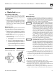
Make sure ground wiring is installed
per wiring diagram. Good
grounding is extremely important
for proper operation.
Solder or water splatter between
plugs and circuit board can cause
improper operation of control
module. Place a shield over the
boiler internal controls and
components during installation.
Control indicator lights
Lockout modes
See Charts 1 through 8 in this manual section for
detailed troubleshooting procedures.
To reset control after a lockout, turn off power at the
120 VAC service switch or turn down all thermostats.
Wait 45 seconds. Then restore power or call for heat.
After an over-temperature lockout (POWER and LIMIT
lights flashing), the control will only reset after
interruption of 120 VAC for 45 seconds.
POWER light flashing alone
Usually indicates reversed polarity of 120 VAC power
wires.
POWER and TSTAT CIRC lights flashing
Usually indicates stray voltage on external thermostat circuit wires or return
water temperature entering boiler sections has not reached 130 °F within
20 minutes.
POWER and LIMIT lights flashing alternately
Usually indicates that limit circuit failed to cut off boiler at high temperature
— return water temperature sensor has sensed water over 235 °F.
POWER and PRESS SWITCH lights flashing
Usually indicates pressure switch is closed when it should not be, or pressure
switch failed to close within 5 minutes of blower starting.
POWER and FLAME lights flashing
Usually indicates control has had three unsuccessful ignition attempts or
sensed flame when it shouldn’t be there.
Non-lockout modes
TSTAT CIRC light flashing alone
Usually indicates return water temperature sensor detects water at boiler
return pipe less than 40 °F. Both internal circulators will run continuously,
even with no call for heat, until temperature rises.
LIMIT light flashing alone
Usually indicates an open or shorted return water temperature sensor.
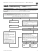
Troubleshooting the control module
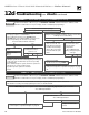
See Figure 29 for location of harness plug receptacles and plugs on the
control module.
Figure 29 Control module harness plug receptacle and indicator light locations
Indicator lights
POWER
TSTAT CIRC
LIMIT
PRESS SWITCH
FLAME
120 VAC IN
120 VAC to transformer
120 VAC to igniter
24 VAC from transformer
47K resistor
24 VAC control circuits
120 VAC to circulators
120 VAC to blower motor
88738
120 VAC to
transformer
120
VAC H
120
VAC N
White
Black
120 VAC IN
120
VAC H
120
VAC N
Ground
White
Green
Black
120 VAC to
blower motor
120
VAC H
120
VAC N
Ground
White
Green
Black
Red wires
to pressure
switch
Blue wire
to gas valve
Yellow wires to
limit control
and block
temp switch
Black wires to
thermostat
circuit
24 VAC control circuits
47K resistor
24 VAC from transformer
24 VAC
Brown
Red
120 VAC to ignitor
120 VAC H
120 VAC N
White
Black
120 VAC
to circulator
White
Green
Ground
120
VAC N
120
VAC H
Black