R02 01/09
AF/AFG Oil Burner Manual RESIDENTIAL BURNERS Potential for Fire, Smoke and Asphyxiation Hazards Incorrect installation, adjustment, or misuse of this burner could result in death, severe personal injury, or substantial property damage. To the Homeowner or Equipment Owner: y Please read and carefully follow all instructions provided in this manual regarding your responsibilities in caring for your heating equipment.
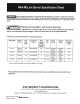
Table of Contents Hazard Def nitions and Owner’s Information ........................................................................................ 3 Information To Be Used Only By Qualif ed Service Technicians General Information ......................................................................................................................................... 4 Table 1 Burner Specification..............................................................................................................
General Information Hazard Definitions Indicates a hazardous situation, which, if not avoided, will result in death or serious injury. ! DANGER Indicates a hazardous situation, which, if not avoided, could result in death or serious injury. ! WARNING Indicates a hazardous situation, which, if not avoided, could result in minor or moderate injury.
General Information To the Owner: Thank you for purchasing a Beckett burner for use with your heating appliance. Please pay attention to the Safety Warnings contained within this instruction manual. Keep this manual for your records and provide it to your qualified service agency for use in professionally setting up and maintaining your oil burner. Your Beckett burner will provide years of efficient operation if it is professionally installed and maintained by a qualified service technician.
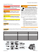
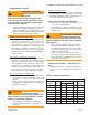
General Specifications Table 2 – Air Tube Combination (ATC) codes Firing Rate (gph) Head (minmax) Static plate size Venturi (inches) ATC Codes for usable air tube lengths (‘A’ in inches; See Figure 3.) 4-1/2 5 5-3/8 6-5/8 7 7-1/4 9 10-1/2 13 16 0.50-0.75 F0 3-3/8U None AF44XR - AF53XR AF65XR - AF72XR AF90XR AF104XR AF130XR A160XR 0.75-1.25 F3 2-3/4U None AF44XN - AF53XN AF65XN - AF72XN AF90XN AF104XN AF130XN AF160XN 0.85-1.
Inspect/Prepare Installation Site Inspect Chimney or Direct Vent System ! WARNING Fire, Smoke & Asphyxiation Hazard y Carefully inspect the chimney or exhaust vent system. y Make sure it is properly sized and in good working condition. y Follow the instructions supplied by the appliance manufacturer.
Inspect/Prepare Installation Site Combustion air supply ! Adequate Combustion WARNING and Ventilation Air Supply Required Failure to provide adequate air supply could seriously affect the burner performance and result in damage to the equipment, asphyxiation, explosion or fire hazards. y The burner cannot properly burn the fuel if it is not supplied with a reliable combustion air source.
Inspect/Prepare Installation Site Prepare the Burner Low Firing Rate Baff e The AFG Low Firing Rate Baffle (LFRB) reduces the air flow and pressure. The LFRB is sometimes used for firing rates under 1.00 gph as listed in Table 4. Refer to the appliance manufacturer’s instructions. Do not omit the LFRB when specified. Omitting the baffle when specified or installing the baffle when not specified could result in impaired burner performance. Burner fuel unit Table 4.
Prepare the Burner 3. If the nozzle is already installed, remove the nozzle line assembly to verify that the nozzle size and spray pattern are correct for the application (per appliance manufacturer’s information). Verify that the electrode tip settings comply with Figure 3. 4. If the nozzle is not installed, obtain a nozzle from the manufacturer, having the capacity and spray angle specified in the appliance manufacturer’s information.
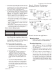
Prepare the Burner Figure 4. Check/Adjust ‘Z’ Dimension for ‘F’ Heads 1-1/8” 1-3/8” ! WARNING Adjust the ‘Z’ dimension to the required specif cation. Incorrect Adjustments could cause combustion problems, carbon deposition from flame impingement, heavy smoke generation and fire hazard. y Make all adjustments exactly as outlined in the following information. Check/Adjust ‘Z’ Dimension - ‘F’ heads 1.
Prepare the Burner Figure 5. Check/Adjust ‘Z’ Dimension - L1 & L2 Heads L1/L2 heads (see Table 7 and Figure 3 for dimensions) 1. See figure above. The important “Z” dimension is the distance from the leading edge of the head to the end of the air tube. This distance for L1 & L2 heads is 1-⅜” if the tube has a straight shroud or 1-¾” if the air tube has a conic shroud. The “Z” dimension is factory set for Figure 6.
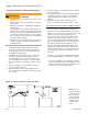
Mount burner on appliance Figure 7. – Mounting Burner in Appliance Figure 8. – Inside Tank Gravity Feed System If space between burner air tube and opening exceeds 1/2 inch, pack burner opening with ceramic fiber refractory. Tilt down 2 o SK8745 Installing the Oil Tank and Supply System ! WARNING Oil Leak and Fire Hazard Figure 9. – Outside Buried Tank-Lift System Install the oil tank following applicable standards in the U.S.
Wire burner ! CAUTION Oil Supply Pressure Control Required Damage to the filter or pump seals could cause oil leakage and a fire hazard. y The oil supply inlet pressure to the burner cannot exceed 3 psig. y Insure that a pressure limiting device is installed in accordance with the latest edition of NFPA 31. y Do NOT install valves in the return line. (NFPA 31, Chapter 8.
Burner Controls GeniSys Model 7505 Control Wiring Explosion, Fire, Scald, and Burn Hazard Fire or Explosion Hazard All heating appliances must have HIGH LIMIT protection to interrupt electrical power and shutdown the burner if operating or safety controls fail and cause a runaway condition. Can cause severe injury, death, or property damage. y The control can malfunction if it gets wet, leading to accumulation of oil or explosive oil vapors.
Burner Controls Typical Burner Sequence of Operation for GeniSys 7505 Control. Refer to the appliance manufacturer’s wiring diagram for actual specifications. 9 1 Pump prime Standby 3 2 4 Trial for ignition Valve-on delay Lockout 5 Ignition carryover 6 8 Motor-off delay 1. Standby: The burner is idle, waiting for a call for heat. 2. Valve-On Delay: The igniter and motor are on while the control delays turning on the oil solenoid valve for the programmed time. 3.
Burner Controls Figure 1 1a. – Interrupted ignition, valve-on delay Figure 1 1b.
Burner Controls Typical Burner Wiring & Burner Sequence of Operation for R7184P Control. Refer to the appliance manufacturer’s wiring diagram for actual specifications. Figure 10. – Typical Burner Wiring 1. STANDBY. The burner is idle, waiting for a call for heat. When a call for heat is initiated, there is a 310 second delay while the control performs a safe start check. 2. VALVE-ON DELAY. The ignition and motor are turned on for a 15 second valve-on delay. 3. TRIAL FOR IGNITION (TFI).
Wire burner Some Thermostats Are Polarity Sensitive. Reversed polarity could cause erratic cycling of the burner control. 3. Set the thermostat substantially above room temperature. 4. Close the line voltage switch to start the burner. If the burner does not start immediately you may have to reset the burner primary control. 5. Initiate a call for heat. 6. After the burner starts, press and hold the reset button for 15 seconds until the yellow light turns on.
Startup/Checkout Startup / Checkout ! 4. After the 60 second recycle period, the control will try to restart the system. WARNING Explosion and Fire Hazard 5. After the 15 second lockout time, the control will lock out the burner and the reset button will flash. Verify that the burner motor and igniter are off and that the burner oil solenoid valve (if used) is not energized.
Perform regular maintenance Step 4: Recheck smoke level. It should be Zero. • This procedure provides a margin of reserve air to accommodate variable conditions. • If the draft level has changed, recheck the smoke and CO2 levels and readjust the burner if necessary Verify the nozzle is the one originally specified by the appliance manufacturer and replace the nozzle with one having the exact specifications from the same manufacturer.
Perform regular maintenance Replace the blower wheel: 1. Turn off all power to the burner before servicing. 2. Disconnect the burner motor wires. 3. Remove the bolts securing the motor to the burner housing. 4. Remove the motor and blower wheel. 5. Remove the existing blower wheel. 6. Referring to the figure below, slide the new blower wheel onto the shaft. y Use a feeler gauge to set the wheel-to-motor gap, as shown below. (AF = 0.125 +1/64 inch, AFG = 0.
21 23 24 6
For best performance specify genuine # Part No. 1 Beckett replacement parts Description # Part No.
Limited WARRANTY For Residential, Commercial and Specialty Burners The R. W. BECKETT CORPORATION (“Beckett”) warrants to persons who purchase its Beckett burners from Beckett for resale or for incorporation into a product for resale (“Customers”) that its equipment is free from defects in material and workmanship under normal use and service for 60 months from the date of manufacture for Residential Burners and 18 months from the date of manufacture for Commercial and Specialty Burners.