Oil Fired Water Boiler Beckett Model NX Burner ! ! Warning–Notice to Owner Please read and follow all instructions on Page 3 in this manual regarding your responsibilities in caring for your heating equipment Contact a qualified service agency for installation and start-up. Incorrect Installation, adjustment, or misuse of this burner could result in severe personal injury, death or substantial property damage.
Table of Contents Hazard Definitions and Owner’s Information ........................................................................................ 3 Information To Be Used Only By Qualified Service Technicians Weil McLain Burner Specification .............................................................................................................. 4 General Information ....................................................................................................................................
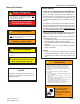
General Information Hazard Definitions ! To the Owner: Thank you for purchasing a Beckett NX burner Danger–Designation Denotes presence of a hazard which, if ignored, will result in death, severe personal injury, and/or substantial property damage. Death, personal Injury, and/or substantial property damage S118 ! Warning–Designation Your NX burner will provide years of efficient operation if it is professionally installed and maintained by a qualified service technician.
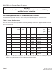
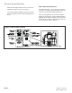
Weil-McLain Burner Specifications NOTICE The remainder of this manual contains Information to be used ONLY by a qualified Service Technician. NX Burner Specifications for Weil-McLain Ultra Oil Boilers Verify that burner specification number (on burner carton) and configuration agrees with information below. Table 1. Burner Configurations The table below provides burner specifications and starting air settings for NX burners applied to Weil-McLain Model UO boilers.
General Specifications General Specifications ! Table 2 – Burner Specifications Capacity LB & LC Firing rate 0.40 – 1.35 GPH Input 56,000 – 189,000 Btu This equipment must be installed, adjusted and put into operation only by a qualified individual or service agency that is: x Licensed or certified to install and provide technical service to oil heating systems.
General Specifications • Notice Special Requirements State and local approvals are shown on burner rating label mounted on the burner housing. For recommended installation practice in Canada, refer to the latest version of CSA Standard B139 & B140. Concealed damage — If you discover damage to the burner or controls during unpacking, notify the carrier at once and file the appropriate claim.
Site Preparation Inspect/Prepare Installation Site • Clearances to Burner and Appliance Provide space around burner and appliance for ease of service and maintenance. Check the minimum clearances against those shown by the appliance manufacturer and by applicable building codes. • Inspect Chimney or Direct Vent System Inspect the chimney or vent. Make sure it is properly sized and in good working condition. Follow the instructions supplied by the appliance manufacturer.
Site Preparation ! • Fuel Line Valves and Filter Warning–Connect Outside Air Duct to NX Adapter. The outside air adapter must be installed by strictly following the kit installation instructions. Do NOT attempt to install outside air piping without using the outside air adapter and instructions provided. Abundant fresh air is required for proper combustion. Failure to install adapter properly could result in impaired combustion, appliance soot-up, puffback of smoke, and fire or asphyxiation hazards.
Burner Preparation Prepare the Burner ! • General In most cases, the burner is ready to mount to the appliance. There can be situations where the burner needs to be reconfigured to perform properly in the appliance. Review the appliance manufacturer’s specifications prior to installing to determine if any modification is required to properly configure the burner. Refer to Table 1. Instruction on how to perform the following burner preparation tasks can be found in the Professional Maintenance section.
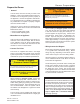
Burner Preparation Figure 3. – Burner Connections.
Burner Preparation Figure 4.
Start the Burner Start the Burner and Set Combustion • Start-up and Initial Settings 1. Open the shutoff valves in the oil supply line to the burner. 2. Referencing Figure 5 verify and/or set the Head/ Air Adjustment Pointer to the value shown in Table 1. This is an initial air setting for the pump bleeding procedure only. Calibrated test instruments must be used for the final head/air adjustment. 3. Set the thermostat substantially above room temperature. 4.
Start the Burner ! Warning–Check for Excess Fuel Accumulation. Do not attempt to start the burner when excess fuel or vapor has accumulated in the appliance. Starting the burner under these conditions could result in a puffback of hot combustion gases, high smoke levels, or otherwise hazardous operation. Could cause death, personal injury and/or substantial property damage due to equipment malfunction, heavy smoke, soot blockage, hot gas puff-back, fire and asphyxiation hazard.
Professional Maintenance Trained Service Technician’s Regular Maintenance While performing routine maintenance check the following. Replace the oil supply line filter. The line filter cartridge must be replaced to avoid contamination of the fuel pump and nozzle. • Inspect the oil supply system. All fittings should be tight and leak-free. The supply lines should be free of water, sludge and other restrictions. • Remove and clean the pump strainer if applicable.
Professional Maintenance • Nozzle Installation Obtain a nozzle having the capacity, spray angle, and pattern specified in the appliance manufacturer’s information or Beckett OEM Specification Guide, Part # 6711. Make certain the correct nozzle is selected for the actual fuel pump pressure. See Table 1. Perform the following steps when replacing a nozzle. 1. Remove the nozzle line assembly to gain access to the nozzle. 6. Protect the nozzle orifice and strainer when installing.
Professional Maintenance • Check the electrode tip settings, as shown in Figure 7. If necessary, adjust by loosening the electrode clamp screw (Figure 8) and slide/rotate the electrodes as necessary. When the adjustment is complete, securely tighten the clamp screw. • Check Retention Head Alignment and Cad Cell Sighting (Refer to Figure 9.) The cad cell sighting holes in both the throttle cup and the retention head must be aligned to allow the cad cell to detect the flame.
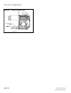
Professional Maintenance • Blower Wheel Replacement For installation or replacement of a blower wheel, insure that there is a space between the blower wheel and the motor face of 0.115”. Refer to Figure 10. Figure 10.
Professional Maintenance Replacement Parts Diagram SK967102 SK9804B For best performance specify genuine Page 18 Beckett SK9803B replacement parts WM 550-141-996/1105 RWB 6104WMNX R1005
Professional Maintenance Part Number designations for Replacement Parts Diagrams on Page 18. Item Description Part No.
Limited WARRANTY For Residential, Commercial and Specialty Burners The R. W. BECKETT CORPORATION (“Beckett”) warrants to persons who purchase its Beckett burners from Beckett for resale or for incorporation into a product for resale (“Customers”) that its equipment is free from defects in material and workmanship under normal use and service for 60 months from the date of manufacture for Residential Burners and 18 months from the date of manufacture for Commercial and Specialty Burners.