
Instruction manual


WM 550-141-996/1105 Page 13
RWB 6104WMNX R1005
Chimney Vent Systems: Install the burner cover
and repeat Steps 2 and 4 above. If CO
2
increas-
es (O
2
decreases), remove the cover and adjust
the air setting so the CO
2
(O
2
) with the cover
installed meets the requirements of Step 3.
Direct Vent Systems with Outside Air Ducted to
Burner: Install the burner cover.
Start and stop the burner several times to ensure
satisfactory operation. Test the primary control
and all other appliance safety controls to verify
that they function according to the manufactur-
er’s specifi cations.
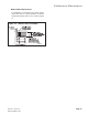
Cover Installation
Install the cover mounting screws in the cover
mounting plate.
Install the cover over the mounting plate while
aligning the side slots with the installed cover
mounting screws.
Direct Vent specifi ed burners include an opening
on the top of the cover for an outside air intake.
4.
5.
6.
•
1.
2.
3.
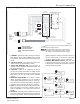
Figure 6. – Burner Cover
SK9804A
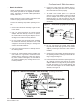
Start the Burner
Warning–Check for Excess
Fuel Accumulation.
Do not attempt to start the burner when excess fuel o
r
vapor has accumulated in the appliance. Starting the burne
r
under these conditions could result in a puffback of hot
combustion gases, high smoke levels, or otherwise
hazardous o
p
eration.
Could cause death, personal
injury and/or substantial
property damage due to
equipment malfunction, heavy
smoke, soot blockage, hot gas
puff-back, fire and asphyxiation
hazard.
S112
!
Step 1: Adjust the head/air until a trace of smoke
is achieved. This can be accomplished by turn-
ing the screw on the head/air adjustment plate
assembly to increase air (CCW) or decrease air
(CW).
Step 2: At the trace of smoke level, measure the
CO
2
(or O
2
) . This is the vital reference point
for further adjustments. Example: 13.5% CO
2
(2.6% O
2
)
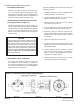
Step 3: Increase the air to reduce the CO
2
by 1.5
to 2 percentage points. (O
2
will be increased by
approximately 2.0 to 2.7 percentage points.) Ex-
ample: Reduce CO
2
from 13.5% to 11.5% (2.6%
to 5.3% O
2
).
Step 4: Recheck smoke level. It should be Zero.
This procedure provides a margin of
reserve air to accommodate variable
conditions.
If the draft level has changed, recheck the
smoke and CO
2
levels and readjust
burner, if necessary.
Step 5: Once the combustion has been set, tight-
en the lower acorn nut and splined nut on the air
adjustment assembly. See Figure 5.
•
•
Set Combustion with Test Instruments
Allow the burner to run for approximately 5 to 10
minutes.
Set the stack draft between -0.01” to
-0.02” w.c. for chimney vent applications. No
draft adjustment required for direct venting.
Follow these fi ve steps to properly adjust the
burner:
•
1.
2.
3.