
Instruction manual


WM 550-141-996/1105 Page 15
RWB 6104WMNX R1005
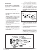
Nozzle Installation
Obtain a nozzle having the capacity, spray angle,
and pattern specifi ed in the appliance manufac-
turer’s information or Beckett OEM Specifi cation
Guide, Part # 6711.
Make certain the correct nozzle is selected for the
actual fuel pump pressure. See Table 1.
Perform the following steps when replacing a noz-
zle.
Remove the nozzle line assembly to gain access
to the nozzle.
Use a ¾” open-end wrench to hold the nozzle
adapter. DO NOT attempt to remove or replace
the nozzle without securing the adapter, as noz-
zle alignment could be seriously affected.
Do not squeeze the electrodes when handling
the nozzle line assembly. Excessive force could
change the electrode tip settings or damage the
ceramic electrode insulators.
Use a 5/8” open-end wrench to carefully remove
the existing nozzle.
Inspect the nozzle adapter before installing the
new nozzle. If it is grooved or scratched on the
sealing surface, replace the nozzle line assem-
bly. If the surface is damaged, oil could leak at
the nozzle to adapter joint, causing serious com-
bustion problems.
•
1.
2.
3.
4.
5.
Protect the nozzle orifi ce and strainer when in-
stalling. If the orifi ce gets dirt in it or is scratched,
the nozzle will not function properly.
To install a new nozzle, place a ¾” open-end
wrench on the nozzle adapter. Insert the nozzle
into the adapter and secure fi nger tight. Finish
tightening with a ⅝” open-end wrench. Use care
to avoid bending the burner head support legs or
electrodes.
6.
7.
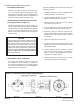
Professional Maintenance
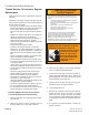
Figure 7. – Electrode tip gap and spacing
5/32” GAP
1/4” above
nozzle center
3/32” Nozzle-to-tip
Spacing
SK9664
Do not over-torque the nozzle when install-
ing. This will cause deep grooves in the nozzle
adapter, preventing a seal when a new nozzle is
installed.
Carefully check and realign the electrode tips af-
ter replacing a nozzle, ensuring the electrode set-
tings comply with Figure 7.
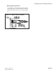
If the head was removed when replacing the noz-
zle, carefully reconnect the head to the nozzle
adapter. Make sure to align the key in the support
leg with the keyway in the nozzle adapter and
to butt the head support to the nozzle adapter
shoulder, see Figure 8.
8.
9.
10.
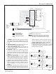
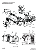
Figure 8. – Nozzle Line/Head/Air Tube Assembly (Low fi ring rate shown.)
Retention Head
Retention Head
Head Support Legs
Head Support Legs
Electrode Tips
Electrode Tips
Electrode Clamp
Electrode Clamp
Electrode Bracket
Electrode Bracket
Electrode Insulator
Electrode Insulator
Electrode Extension Rods
Electrode Extension Rods
Nozzle Adapter
Nozzle Adapter
Nozzle
Nozzle
Stops in Retention Ring
Stops in Retention Ring
Retention Ring
Retention Ring
Throttle Ring
Throttle Ring
Throttle Cup
Throttle Cup
Nozzle Line
Nozzle Line
Bulkhead Fitting
Bulkhead Fitting
SK9666A
SK9666A
SK9666A