
Instruction manual

Part number 550-100-116/0714
19
SlimFit
™
COMMERCIAL CONDENSING GAS-FIRED WATER BOILER
— Boiler Manual
Install water piping (continued)
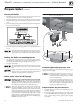
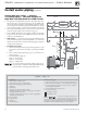
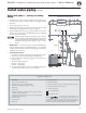
&IGURE Pump zoning plus optional DHW piping
— primary/secondary piping
SF3009
ZONE 1
2
6 6
6 10
6
6
6
14
14
10
8
9
5
10
6
11
20
Additional
Zones
11
11
6
10
6 6
11
12
Do not exceed
8 pipe diameters
apart
21
1
Boiler
outlet
Boiler
return
3
4
26
NOTE 1
33
Zoning with pumps — primary/secondary
piping
1. Connect boiler to system as shown in Figure18 when pump zoning.
e boiler pump cannot be used for a zone. It must supply only the
boiler loop.
2. Install a separate pump for each zone.
3. When using a closed-type expansion tank, connect the expansion tank
and make-up water piping as shown in Figure15, page16.
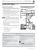
4. Connect DHW (domestic hot water) piping to indirect storage water
heater as shown. Connect from the DHW tank aquastat to the DHW
terminals on the SlimFit boiler.
DHW tanks piped using this arrangement need to be sized
for the required load, with a DHW pump selected to provide
a ow rate through the boiler and tank that is within the al-
lowable ow rate range listed in Figure13, page15 of this
manual.
5.
$(7PRIORITY Set the Sola control for the desired DHW priority
mode. Set the boiler pump to be OFF during DHW it is not needed.
e ow/check valve shown on the boiler outlet piping prevents gravity
circulation in the boiler loop.
6.
#ONTROLLINGTHEPUMPS
a. e Sola can control up to three pumps. In this application, set the
Sola control to operate the boiler pump and DHW pump.
b. Refer to Field wiring, beginning on page51, for instructions on
wiring to pumps.
c. e factory default seings are:
Pump A Boiler pump
Pump C DHW pump.
d. e zone pumps in Figure18 must be controlled by pump relays
activated by the zone thermostats or zone controller.
Legend — Figure 18
1 SlimFit boiler
2 Indirect water heater (DHW), if used
3 Boiler relief valve (see page14 for piping details)
4 Relief valve discharge piping (see page14 for details)
5 DHW pump
6 Isolation valves
8 Diaphragm (or bladder) type expansion tank (see page16 for piping of
closed-type expansion tank, if used)
9 Air separator [with automatic air vent only on systems using diaphragm
(or bladder) type expansion tank]
10 Flow/check valves
11 Purge/drain valves
12 Boiler pump
14 Zone pumps, typical
20 Make-up water supply
21 Primary/secondary connection (tees no more than 8 pipe diameters apart)
26 External drain/blowdown valve, when used
33 Strainer, recommended
Items supplied with boiler
Items supplied by others
NOTE 1:
Use at least 3-inch schedule 40 pipe on all
boiler loop piping (connecting boiler to and
from the primary/secondary connection, item21). Pipe sizing is based on a
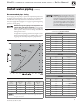
temperature rise of 30°F, corresponding to the recommended maximum ow
rate. Failure to follow these guidelines could result in system problems.