
Instruction manual


Part number 550-100-116/0714
44
SlimFit
™
COMMERCIAL CONDENSING GAS-FIRED WATER BOILER
— Boiler Manual
DIRECT VENT — Sidewall (continued)
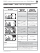
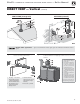
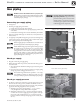
&IGURE Direct venting — install tee on air inlet or provide means
to disassemble the air piping to allow access to the inlet
air filter
1 Vent/air pipe manufacturer’s
SlimFit Vent/Air Adapter,
8-inch outlet
2 Vent/air pipe manufacturer’s
tee, 8-inch orient the tee
so the cover will be on the
same side as the boiler heat
exchanger cleanout cover
3 Air pipe connection, 8-inch
add vent/air pipe manufac-
turer’s reducer if using 6-inch
air piping
4 Vent/air pipe manufacturer’s
cover, 8-inch
5 Vent piping (a vent/air pipe
manufacturer’s SlimFit Vent/
Air Adapter must be installed
at the boiler vent connection)
Use only the vent/air piping ma-
terials listed in Figure28, page31.
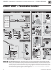
&IGURE Multiple terminations — clearance from
vent of one to air intake of the next
(normal and snorkel layouts)
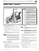
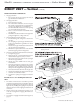
&IGURE DIRECT VENT — sidewall termination
assembly
1 Vent piping — insert from
the outside until the female
end shoulder rests against
the outside stop plate
2 Air piping — insert from
the outside until the female
end shoulder rests against
the outside stop plate
3 Sidewall termination plates
(hole must be just larger
than the pipe diameter)
4 Vent termination elbow
— use outward-facing
90-degree elbow as shown
5 Air termination elbow — use
down-turned 90-degree
elbow as shown
6 Corrosion-resistant thimble,
by installer
7 Bird screens, by installer
8 Vent length
9 Elbow
3. Vent pipe penetration:
a. Cut a hole for the vent pipe.
b. For combustible construction, size the vent pipe hole at least ” larger
than the vent pipe diameter, or larger if specied by the vent manufacturer.
c. For noncombustible construction, size the opening per vent manufac-
turer instructions.
d. Insert a corrosion-resistant metal thimble in the vent pipe hole as shown
in Figure34.
e. Follow all local codes for isolation of vent pipe when passing through
oors or walls.
4. Figure42 Provide and install corrosion-resistant metal stop plates (item3)
as shown.
a. e hole size in the stop plates must be just larger than the vent pipe
diameter.
b. Obtain stop plates ONLY from the vent pipe manufacturer.
5. Insert the last lengths of vent and air pipe from the outside. e shoulders
of the vent and air pipe female ends must rest against the outer stop plates as
shown. e plates must prevent the vent or air pipe from being pushed inward.
6. e vent and air pipes may run up as high as 4 feet with no enclosure. e
vent and air pipes must be secured with braces, and all clearances and lengths
must be maintained. Space braces no further than 24 inches apart.
7. External venting greater than 4 feet requires an insulated enclosure around the
vent and air pipes. e vent and air terminations must exit through the enclo-
sure as shown in the illustration above, maintaining all required clearances.
8. Aach the exterior piping and termination elbows.
9. Install a vent/air pipe manufacturer’s bird screen in the open end of the vent
termination elbow and air termination elbow.
10. Seal exterior openings thoroughly with exterior caulk.
11. For multiple boiler terminations, see Figure41.
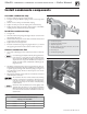
Provide access for cleaning the boiler air inlet
1. e boiler air inlet must be accessible for period examination and cleaning
of the air inlet lter. is can be done by installing an 8-inch capped tee as
shown in Figure40 or by installing the air piping in a way that will allow
disconnection of the air piping from the boiler air connection.
2. Install a pipe size reducer on top of the tee if using 6-inch air piping. DO
NOT use a 6-inch tee.
3. Use only the air piping materials listed in Figure28, page31.