Beckett Model NX Burners Oil Fired Water Boiler Instruction Manual WARNING Potential for Fire, Smoke and Asphyxiation Hazards Incorrect installation, adjustment, or misuse of this burner could result in death, severe personal injury, or substantial property damage. To the Homeowner or Equipment Owner: Please read and carefully follow all instructions provided in this manual regarding your responsibilities in caring for your heating equipment.
To the Owner: Thank you for purchasing a Beckett burner for use with your heating appliance. Please pay attention to the Safety Warnings contained within this instruction manual. Keep this manual for your records and provide it to your qualified service agency for use in professionally setting up and maintaining your oil burner. Your Beckett burner will provide years of efficient operation if it is professionally installed and maintained by a qualified service technician.
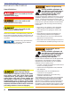
Section: General Information General Information Hazard Definitions Indicates a hazardous situation, which, if not avoided, will result in death or serious injury. Indicates a hazardous situation, which, if not avoided, could result in death or serious injury. Owner’s Responsibility Incorrect installation, adjustment, and use of this burner could result in severe personal injury, death, or substantial property damage from fire, carbon monoxide poisoning, soot or explosion.
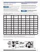
Section: Weil-McLain Burner Specifications Weil-McLain Burner Specifications NX Burner Specifications for Weil-McLain Ultra Oil Boilers Fozen Plumbing and Water Damage Hazard. Unoccupied residences in severly cold weather could experience frozen plumbing in just a few hours if the heating system fails for any reason.
Section: General Information & Inspect/Prepare Installation SIte General Information Certifications/approvals Table 2. – Burner Specifications Capacity LB & LC Firing rate: 0.40 – 1.35 GPH Input: 56,000 – 189,000 Btu Capacity LD & LF Firing rate: 1.10 - 1.75 GPH Input: 154,000 – 245,000 Btu/h Fuels U. S. No. 1 or No. 2 heating oil only (ASTM D396) Canada No. 1 stove oil or No. 2 furnace oil only Underwriters Laboratories has certified this burner to comply with ANSI/UL 296 and CSA-B139.
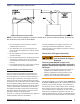
Section: Inspect/Prepare Installation SIte Figure 2 – Chimney Design - Above the Roof NOTE: Correct chimney design is shown by dotted lines. Incorrect chimney design, as shown by the solid lines, may result in down-drafts. 3. Any accumulation of soot or debris in chimney offsets should be removed 4. Any obstructions such as a protruding joint or a piece of broken tile wedged in the chimney should be removed. 5. No other appliance connection should be made to the same flue pipe. 6.
Section: Inspect/Prepare Installation SIte Exhaust fans and other air-using devices: Size air openings large enough to supply all air-using devices in addition to the minimum size required for combustion air. If there is any possibility of the equipment room developing a negative pressure due to exhaust fans, clothes dryers, etc., either pipe combustion air directly to the burner or provide a sealed enclosure for the burner and supply it with its own combustion air supply.
Section: Inspect/Prepare Installation SIte 3. The end of the air tube should normally be ¼” back from the inside wall of the combustion chamber. Never allow the leading edge of the head assembly to extend into the chamber, unless otherwise specified by the heating appliance manufacturer. Carefully measure the insertion depth when using an adjustable flange. Verify the insertion depth when using a welded flange.
Section: Inspect/Prepare Installation SIte Figure 6. – Outside Buried Tank-Lift System To further protect the fuel supply system and reduce nozzle orifice plugging with firing rates below 0.75 gph, a dual filtration system can be installed. This typically consists of a 50 micron primary filter, located near the fuel tank and a secondary filter rated for at least 10 microns located near the burner.
Section: Inspect/Prepare Installation SIte Figure 7a. – GeniSys 7505 Control interrupted ignition, valve-on delay only (no motor-off delay) R IGNITER IGNITER L2 (IGN) MOTOR L2 (MTR) MOTOR y Verify all limit and safety controls are installed and functioning correctly, as specified by the manufacturer, applicable safety standards, codes and all authorities having jurisdiction.
Section: Burner Control Burner Control and repeats the ignition sequence. The control will continue to Recycle each time the flame is lost, until it reaches a pre-set time allotment. The control will then go into Hard Lockout instead of recycle. This feature prevents excessive accumulation of oil in the appliance firing chamber. Fire or Explosion Hazard Can cause severe injury, death, or property damage. y The control can malfunction if it gets wet, leading to accumulation of oil or explosive oil vapors.
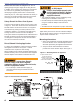
Section: Burner Control Figure 8. GeniSys Model 7505 Control Wiring Connections Reset Button with Red Light Yellow Light Green Light Cad Cell Connections Communication Port 2 Thermostat Terminals Communication Port 1 Optional Components: Contractor’s Tool: Hand-held device for programming and diagnostics Display Module: Permanent device for programming and diagnostics Alarm Module: For adding isolated low voltage alarm contacts to the base control. See Alarm Module Instructions for specifications.
Section: Burner Control Figure 9. Typical Burner Wiring & Burner Sequence of Operation for R7184P Control. Refer to the appliance manufacturer’s wiring diagram for actual specifications. SK9359 1. STANDBY. The burner is idle, waiting for a call for heat. When a call for heat is initiated, there is a 3-10 second delay while the control performs a safe start check. 2. VALVE-ON DELAY. The ignition and motor are turned on for a 15 second valve-on delay. 3. TRIAL FOR IGNITION (TFI). The fuel valve is opened.
Section: Start the Burner and Set Combustion Start the Burner and Set Combustion Explosion and Fire Hazard Failure to follow these instructions could lead to equipment malfunction and result in heavy smoke emission, soot-up, hot gas puff-back, fire and asphyxiation hazards. Start-up and Initial Settings 1. Open the shutoff valves in the oil supply line to the burner. 2. Referencing Figure 9, verify and/or set the Head/Air Adjustment Pointer to the value specified by the Appliance Manufacturer.
Section: Start the Burner and Set Combustion Step 2: At the trace of smoke level, measure the CO2 (or O2) . This is the vital reference point for further adjustments. Example: 13.5% CO2 (2.6% O2) 1. Allow the burner to run for approximately 5 to 10 minutes. The NX burner has a reduced diameter air tube, precisiondesigned air throttle cup and combustion head for improved performance.
Section: Trained Service Technician’s Regular Maintenance Cover Installation 1. Install the four cover mounting thumb screws in the cover mounting plate. 2. Install the cover over the mounting plate while aligning the side slots with the installed cover mounting screws. Figure 11. – Burner Cover SK9804A The following guidelines are provided for routine maintenance. ○ Replace the oil supply line filter. The line filter cartridge must be replaced to avoid contamination of the fuel pump and nozzle.
Section: Trained Service Technician’s Regular Maintenance ○ ○ ○ ○ ○ ○ ○ ○ Check the pump pressure and cutoff function. Check primary control safety lockout timing. Check ignition system for proper operation. Inspect and clear the vent system and chimney of any soot accumulation or other restriction. Clean all flue passages and flue pipe. Replace corroded or damaged pipes. Clean the appliance thoroughly according to the manufacturer’s recommendations. Check the burner performance.
Section: Trained Service Technician’s Regular Maintenance Perform the following steps when replacing a nozzle. 1. Remove the nozzle line assembly to gain access to the nozzle. 2. Use a 3/4” open-end wrench to hold the nozzle adapter. DO NOT attempt to remove or replace the nozzle without securing the adapter, as nozzle alignment could be seriously affected. 3. Do not squeeze the electrodes when handling the nozzle line assembly.
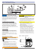
Section: Trained Service Technician’s Regular Maintenance Check Retention Head Alignment and Cad Cell Sighting (Refer to Figure 13.) The cad cell sighting holes in the throttle cup and the retention head must be aligned to allow the cad cell to detect the flame. Make sure the stamped key in the retention head collar lines up with the keyway in the nozzle adapter when mounting the retention head. Note that in specific applications, the retention head may not have a sighting hole.
Section: Trained Service Technician’s Regular Maintenance Figure 13. – Retention Head/Throttle Cup Alignment Figure 14.
Section: Replacement Parts Replacement Parts For best performance specify genuine Beckett replacement parts 15 11a 11c 25 21 19 4 9 11b 22 20 26 23 17 16 1 6 5 24 8 2 11d 7 10 22
Section: Replacement Parts Item Description 1 Head/Air adjustment mechanism assembly 2 Air guide 3 Gasket, mounting flange (not shown) 4 Air tube combination, (Includes Screws, air tube mounting #8 x 3/8) 5 Blower wheel 6 Connector tube assembly, 11” 7 Coupling 8 Door, rear access 9 Electrode insulator kit 10 CleanCut Fuel Pump, (Requires Mounting Screws ¼ -20 x 7/8”) 11a Gasket, igniter baseplate 11b Gasket, igniter baseplate hinge 11c Gasket, wiring 11d Gasket, rear access door 15 Igniter, electronic 16
Limited Warranty Information The R. W. BECKETT CORPORATION (“Beckett”) warrants to persons who purchase its “Products” from Beckett for resale, or for incorporation into a product for resale (“Customers”), that its equipment is free from defects in material and workmanship. To qualify for warranty benefits, products must be installed by a qualified service agency in full compliance with all codes and authorities having jurisdiction, and used within the tolerances of Beckett’s defined product specifications.