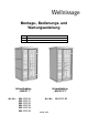
Montage-, Bedienungs- und Wartungsanleitung en fr it ASSEMBLY, USER AND MAINTENANCE INSTRUCTIONS NOTICE DE MONTAGE, D'UTILISATION ET D'ENTRETIEN ISTRUZIONI DI MONTAGGIO, USO E MANUTENZIONE Infrarotkabine „AktiVit 1“ Art.-Nr.: 554.1111.10 554.1111.11 554.1111.12 554.1111.13 554.1111.14 554.1111.15 Infrarotkabine „AktiVit C1“ Art.-Nr.: Stand: 1320 554.1111.
- de Sehr geehrte Kundin, sehr geehrter Kunde, lesen Sie diese Anleitung vor dem Aufbau der Infrarotkabine vollständig durch, um Montagefehler oder Beschädigungen zu vermeiden. Prüfen Sie sofort anhand der Packliste, ob die Kabine unbeschädigt und vollständig bei Ihnen angekommen ist. Bitte vernichten Sie die Packliste erst nach Ablauf der Garantiezeit. Diese Liste dient Ihnen zur Kontrolle auf Vollständigkeit der Einzelteile und ist mit dem Kaufbeleg aufzubewahren.
Das Warnschild WARNUNG! Im Bodenelement und in den Wandelementen befinden sich großflächige Heizsysteme mit 230V Netzspannung. Nach erfolgtem Aufbau der IR – Kabine gemäß Montageanleitung ist das Einbringen von Schrauben, Nägeln, Heftklammern etc.
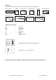
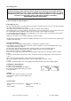
Werkzeug Folgendes Werkzeug sollten Sie vor Beginn der Montage zurecht gelegt haben. Wasserwaage Inbusschlüssel Rollmaß Bohrmaschine Universalmesser Elektroschrauber Hammer Bleistift Schraubendreher Feinsäge / Handkreissäge Abkürzungen / Symbole: FW SW RW - Frontwand Seitenwand Rückwand cm mm max ca. - Zentimeter Millimeter maximales Maß circa - Bedienungsanleitung der IR-Steuerung beachten! - Leitung von Pos.
Montagebedingungen für Wellnissage - Montageteam Wenn Sie Montagehilfe in Anspruch nehmen und dazu ein Wellnissage - Montageteam rufen, werden wir für Sie wie folgt tätig: Montage bedeutet das anleitungsgemäße Zusammenfügen (Aufbau) der gelieferten Einzelteile der Ware ohne Anstrich, Lieferung und Montage von Zubehör und Zubehörteilen. Elektrische Anschlüsse sind in den Montageleistungen nicht enthalten Die aufzubauende Ware muss sich am Aufbauort/ Standort/ Standfläche befinden.
- en Dear customer Read these instructions thoroughly before installing your infrared cabin in order to avoid installation errors or damage. Use the packing list to check immediately that you have received the cabin undamaged and complete. Please do not dispose of the packing list before the guarantee period has expired. This list enables you to check that all the individual parts are present and is to be retained with your proof of purchase.
The warning label WARNING! Extensive heating systems with 230 V mains voltage are located in the floor and wall elements. After the infrared cabin has been set up in accordance with the assembly instructions, it is strictly prohibited to install screws, nails, staples and the like in the cabin elements, as well to partially or completely cover the heating surfaces (with towels or pillows, for example). FIRE HAZARD, RISK OF FATAL INJURY! is to be attached as shown in figure 13.
Tools You should have the following tools to hand before beginning assembly. Spirit level Tape measure Allen key Drill Universal cutter Electric screwdriver Hammer Pencil Screwdriver Mitre saw / hand disk saw Abbreviations / Symbols: FW SW RW - Front wall Side wall Rear wall cm mm max ca. - Centimetre Millimetre Maximum dimension approximately/approx.
A Assembly conditions for a Wellnissage assembly team If you need help assembling your cabin and choose to employ a Wellnissage assembly team, we will carry out the following services for you: Assembly means putting together (installation) of the individual parts supplied. It does not include treating them with a wood protection agent, the delivery and assembly of accessories and accessory parts. Electrical connections are not included in the assembly service.
- fr Chère cliente, cher client, Lisez attentivement la présente notice avant de procéder à l'assemblage de la cabine thermique à infrarouge afin d’éviter toute erreur de montage ou d’éventuels dommages. Contrôlez immédiatement à l’aide de la liste de colisage que la cabine vous est bien parvenue intacte et complète. Ne détruisez la liste de colisage qu'une fois la garantie écoulée.
Le panneau d'avertissement ATTENTION ! De larges systèmes de chauffage fonctionnant à une tension d'alimentation de 230 V se trouvent dans l'élément de sol et dans les éléments de paroi. Une fois la cabine IR – conformément à la notice de montage – assemblée, il est formellement interdit de fixer des vis, clous, agrafes, etc.
Outils Pour le montage, nous vous recommandons de préparer les outils suivants. décamètre à ruban niveau à bulle clé pour vis à six pans creux perceuse couteau universel visseuse électrique marteau crayon Tournevis scie à denture fine / scie circulaire Abréviations / Symboles: FW SW RW - paroi avant paroi latérale paroi arrière cm mm max ca. - centimètres millimètres cote maximale environ / env. - Respecter la notice d'utilisation de la commande IR ! - Câble de rep.
Conditions de montage pour l'équipe de montage Wellnissage Si vous décidez de vous faire aider pour le montage et que vous faites appel à l'équipe de montage Wellnissage, nous prendrons en charge les éléments suivants à votre place : Le montage, ce qui signifie l'assemblage conforme aux instructions (montage) des pièces détachées livrées pour la marchandise sans application de produit, la livraison et le montage des accessoires.
- it Egregi clienti, si prega di leggere attentamente le presenti istruzioni per l'uso, prima di montare la cabina a raggi infrarossi, al fine di evitare errori di montaggio o danneggiamenti. Controllare subito con l'ausilio della lista di imballaggio che la cabina sia stata fornita completa e senza danni. Conservare la lista di imballaggio fino alla scadenza del periodo di garanzia. Questa lista serve per controllare la completezza della fornitura e deve essere conservata insieme allo scontrino.
La targhetta di avvertenza ERTENZA! Nell’elemento pavimento e negli elementi parete si trovano sistemi riscaldanti di grandi dimensioni con tensione di rete da 230 V. Dopo il montaggio della cabina a raggi infrarossi in base alle istruzioni, è rigorosamente vietato applicare sugli elementi della cabina viti, chiodi, punti metallici, ecc.
Utensili Prima di iniziare con il montaggio tenere a portata di mano i seguenti utensili. Livella ad acqua metro a nastro chiave a brugola trapano coltello universale avvitatore elettrico martello Matita cacciavite sega fine / sega circolare portatile Abbreviazioni / Simboli: FW SW RW - parete frontale parete laterale parete posteriore cm mm max ca. - Centrimetri Millimetri Dimensioni massime circa / ca. - rispettare le istruzioni per l'uso del comando IR! - cavo da pos.
Condizioni di montaggio per Wellnissage – squadra di montaggio Se avete bisogno di aiuto per il montaggio e chiamate perciò una squadra di montaggio Wellnissage, interverremo alle seguenti condizioni: Per montaggio si intende l’assemblaggio conforme alle istruzioni (installazione) dei singoli componenti forniti senza verniciatura, consegna e montaggio di accessori o parti di accessori. L’allacciamento elettrico non è compreso nel montaggio.
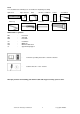
Pos Bild Anzahl [Stück] Abmessung [mm] ELEGANCE 1 CREATE 1 1119 x 1053 1 1 1075 x 1922 1 1 910 x 1922 1 1 910 x 1922 1 1 1075 x 1010 1 1 725 x 1922 1 1 90 x 1170 1 1 90 x 1070 2 2 B554.01.0001 B554.01.0002 B554.01.0003 B554.01.0004 B554.01.0005 B554.01.0006 B554.01.0007 B554.01.0008 Technische.
Pos Bild Anzahl [Stück] Abmessung [mm] ELEGANCE 1 CREATE 1 59/59/1911 1 1 32/30/1911 1 1 60/79/1911 1 1 50/41/1922 1 1 18,5/25/1920 2 2 14/20/1922 3 3 18,5/30/380 1 1 18,5/48/665 1 1 G554.01.0001 G554.01.0002 G554.01.0018 G554.01.0005 G554.01.0006 G554.01.0007 G554.01.0008 G554.01.0009 Technische.
Pos Bild Anzahl [Stück] Abmessung [mm] ELEGANCE 1 CREATE 1 18,5/30/1010 2 2 11/41/300 1 1 3,2/1110/1028 1 1 30/30/150 2 2 ∅125 1 1 114/500/950 1 1 410 x 930 1 1 18,5/29/400 2 2 G554.01.0012 G554.01.0010 G554.01.0011 G519.01.0039 K554.0100.0000 B554.01.0009 B548.03.0004 G554.01.0013 Technische.
Pos Bild Anzahl [Stück] Abmessung [mm] ELEGANCE 1 CREATE 1 30/30/400 2 2 18,5/29/440 2 2 19/24/795 7 7 19/24/615 14 14 8/650/1882 1 1 8/320/1933 1 1 1 1 1 1 G554.01.0014 G548.01.0003 G548.01.0011 G548.01.0005 K107.6518.0000 K107.3219.0000 15 m Technische.
Pos Bild Abmessung [mm] Anzahl [Stück] ELEGANCE 1 CREATE 1 1 1 2 2 2 2 27/667/1030 2 - 27/660/1030 1 - 27/667/1030 2 - 27/660/1030 1 - 10/1030/1935 - 2 SWR/UM SWR/O SWL/UM SWL/O Technische.
Pos Bild Technische.
Pos Bild ELEGANCE 1 CREATE 1 2,5 x 16 20 20 1,6 x 30 50 50 1 1 2 2 1 1 2 2 1 1 1 1 4,5 x 70 3,5 x 15 Technische.
Pos Bild ELEGANCE 1 CREATE 1 3,9 x 25 4 4 Ø 12mm 4 4 1 1 1 1 1 1 1 1 1 1 120 x 40 Technische.
Pos Bild Technische.
ELEGANCE 1 CREATE 1 Technische.
ELEGANCE 1 Technische.
CREATE 1 Technische.
Technische.
Technische.
Technische.
Technische.
ELEGANCE 1 Technische.
CREATE 1 Technische.
ELEGANCE 1 Technische.
ELEGANCE 1 Technische.
ELEGANCE 1 Technische.
CREATE 1 Technische.
Abbildung: ELEGANCE 1 Technische.
Abbildung: ELEGANCE 1 Technische.
Abbildung: ELEGANCE 1 Technische.
de Darstellung ohne Elektroteile en Representation without electrical parts fr schéma sans pièces électriques it Rappresentazione senza parti elettriche Abbildung: ELEGANCE 1 Technische.
Abbildung: ELEGANCE 1 Technische.
Abbildung: ELEGANCE 1 Technische.
Technische.
- de Netzanschluss 230VAC Steckdose Heizkreis 1 Wandelement SW-rechts - Heizkreis 2 nicht belegt Wandelement SW-links Bodenelement FS1 Heizkreis 3 Wandelement RW nicht belegt Dauerspannung 230VAC ( max.60W) Netzanschluss Modul Farblicht Licht Kabinenbeleuchtung Deckenelement, außen Sicherheitskreis - Bussystem nicht belegt ( optional ) Bedieneinheit Modul Farblicht Folienfühler Wandelement RW Raumfühler Deckenelement, innen Technische.
- en - AC 230 V mains connection Socket Heating circuit 1 Wall element (right SW) - Heating circuit 2 Not assigned Wall element (left SW) FS1 floor element Heating circuit 3 Wall element RW Not assigned Continuous voltage AC 230 V (max.
- fr - Raccordement secteur 230 VAC Prise Circuit de chauffage 1 Élément de paroi SW - droite Non affecté Circuit de chauffage 2 Élément de paroi SW - gauche Élément de sol FS1 Circuit de chauffage 3 Élément de paroi RW - Non affecté Tension permanente 230 VAC (max.
- it Collegamento di rete 230 V CA Presa Circuito di riscaldamento 1 Elemento parete SW - destra - Circuito di riscaldamento 2 Non occupato Elemento parete SW - sinistra Elemento pavimento FS1 Circuito di riscaldamento 3 Elemento parete RW - Non occupato Tensione continua 230 V CA (max.
Technische.
de Darstellung ohne Elektroteile en Representation without electrical parts fr schéma sans pièces électriques it Rappresentazione senza parti elettriche Abbildung: ELEGANCE 1 Technische.
Abbildung: ELEGANCE 1 Technische.
Technische.
Abbildung: ELEGANCE 1 Technische.
Technische.
Technische.
Technische.
12 mm Technische.
Technische.
weka Holzbau GmbH, Johannesstr. 16 D-17034 Neubrandenburg Tel. : +49 (0)395 42908-0 Fax : +49 (0)395 42908-83 MA Art.-Nr.: 800.0286.06.92 T2 – 20.34 Technische.