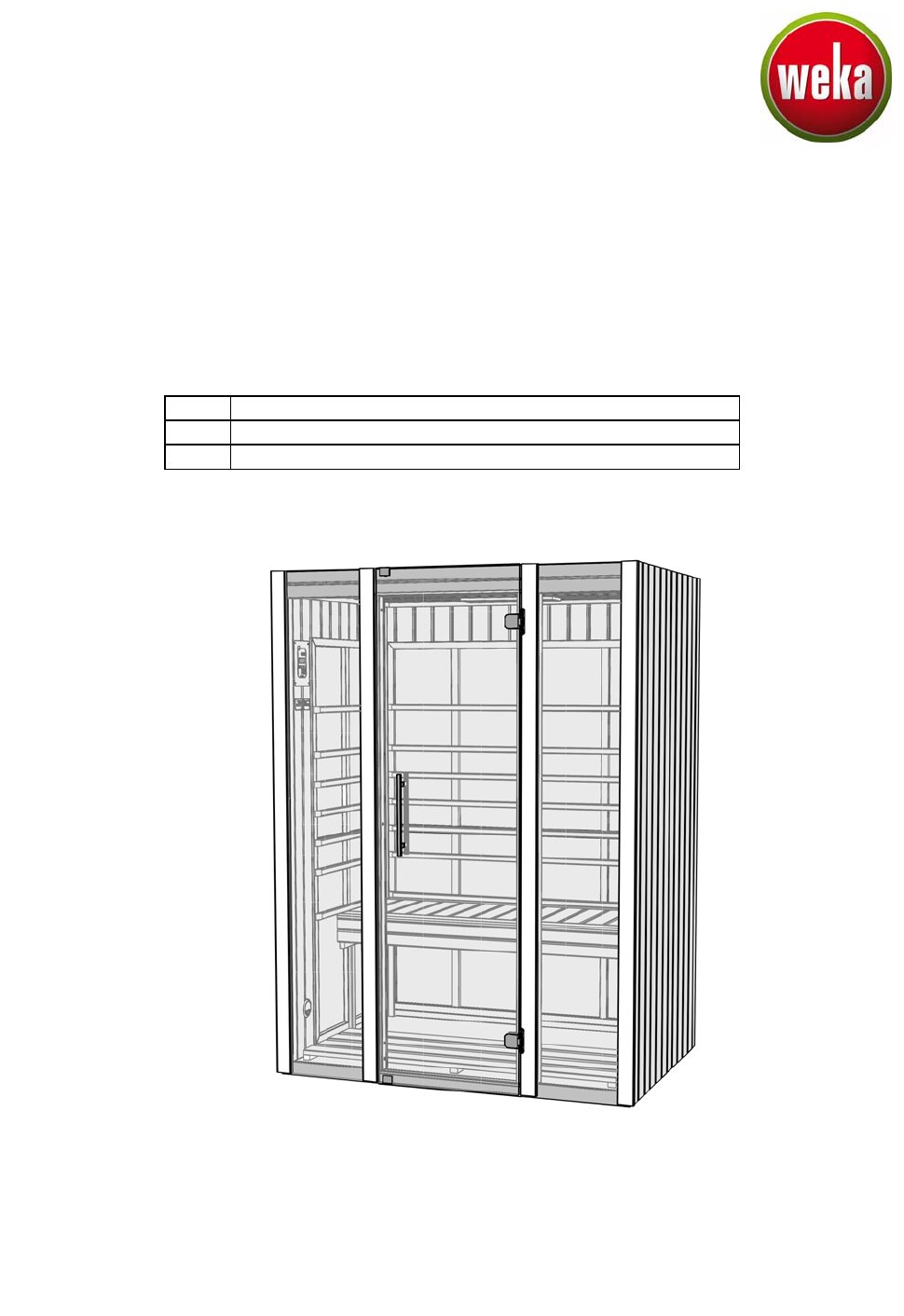
Montage-, Bedienungs- und Wartungsanleitung en fr it ASSEMBLY, USER AND MAINTENANCE INSTRUCTIONS NOTICE DE MONTAGE, D'UTILISATION ET D'ENTRETIEN ISTRUZIONI DI MONTAGGIO, USO E MANUTENZIONE Infrarotkabine Art.-Nr.: 556.1310.
- de Sehr geehrte Kundin, sehr geehrter Kunde, lesen Sie diese Anleitung vor dem Aufbau der Infrarotkabine vollständig durch, um Montagefehler oder Beschädigungen zu vermeiden. Prüfen Sie sofort anhand der Packliste, ob die Kabine unbeschädigt und vollständig bei Ihnen angekommen ist. Bitte vernichten Sie die Packliste erst nach Ablauf der Garantiezeit. Diese Liste dient Ihnen zur Kontrolle auf Vollständigkeit der Einzelteile und ist mit dem Kaufbeleg aufzubewahren.
Die Warnschilder WARNUNG! Im Bodenelement und in den Wandelementen befinden sich großflächige Heizsysteme mit 230V Netzspannung. Nach erfolgtem Aufbau der IR – Kabine gemäß Montageanleitung ist das Einbringen von Schrauben, Nägeln, Heftklammern etc.
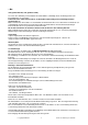
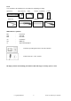
Werkzeug Folgendes Werkzeug sollten Sie vor Beginn der Montage zurecht gelegt haben. Wasserwaage Inbusschlüssel Rollmaß Bohrmaschine Elektroschrauber Universalmesser Hammer Bleistift Schraubendreher Abkürzungen / Symbole: FW SW RW - Frontwand Seitenwand Rückwand cm mm ca. - Zentimeter Millimeter circa - Bedienungsanleitung der IR-Steuerung beachten! - Leitung von Pos.1 = Bodenelement Wir wünschen Ihnen viel Spaß beim Aufbau und jahrelange Freude an Ihrer Wärmekabine.
Garantiebestimmungen der weka Holzbau GmbH Wir gewähren Ihnen zu nachfolgenden Konditionen – jedoch nur auf die Holzteile unserer Produkte (wekaProdukt genannt), nicht auf damit verbundene Bauteile oder Bestandteile des weka-Produkts aus anderem Material als Holz – ab Lieferdatum 5 Jahre Garantie auf Funktion. Innerhalb der Garantiezeit werden fehlerhafte Teile oder fehlende Teile der Ware oder die Ware selbst nach unserer Wahl ersetzt.
- en Dear customer Read these instructions thoroughly before installing your infrared cabin in order to avoid installation errors or damage. Use the packing list to check immediately that you have received the cabin undamaged and complete. Please do not dispose of the packing list before the guarantee period has expired. This list enables you to check that all the individual parts are present and is to be retained with your proof of purchase.
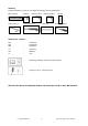
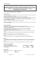
The warning signs WARNING! Extensive heating systems with 230 V mains voltage are located in the floor and wall elements. After the infrared cabin has been set up in accordance with the assembly instructions, it is strictly prohibited to install screws, nails, staples and the like in the cabin elements, as well to partially or completely cover the heating surfaces (with towels or pillows, for example). FIRE HAZARD, RISK OF FATAL INJURY! are to be attached according to figure 11 and figure 13.
Tools You should have the following tools to hand before beginning assembly. Spirit level Tape measure Allen key Drill Electric screwdriver Universal cutter Hammer Pencil Screwdriver Abbreviations / Symbols: FW SW RW - Front wall Side wall Rear wall cm mm ca. - Centimetre Millimetre approximately/approx. - Follow the operating instructions of the IR controller! - Cable from item 1 = floor element We hope you have fun installing your thermal cabin and enjoy it for many years to come.
Warranty terms of weka Holzbau GmbH We guarantee the function of our products for 5 years from the date of delivery based on the following conditions – however only on the wooden parts of our products (hereinafter weka product) and not on connected components or parts of the weka product made of another material besides wood. Within the warranty period defective parts or missing parts of the product or the product itself will be replaced at our discretion.
- fr Chère cliente, cher client, Lisez attentivement la présente notice avant de procéder à l'assemblage de la cabine thermique à infrarouge afin d’éviter toute erreur de montage ou d’éventuels dommages. Contrôlez immédiatement à l’aide de la liste de colisage que la cabine vous est bien parvenue intacte et complète. Ne détruisez la liste de colisage qu'une fois la garantie écoulée.
Les panneaux d'avertissement ATTENTION ! De larges systèmes de chauffage fonctionnant à une tension d'alimentation de 230 V se trouvent dans l'élément de sol et dans les éléments de paroi. Une fois la cabine IR – conformément à la notice de montage – assemblée, il est formellement interdit de fixer des vis, clous, agrafes, etc.
Outils Pour le montage, nous vous recommandons de préparer les outils suivants. décamètre à ruban niveau à bulle clé pour vis à six pans creux visseuse électrique perceuse couteau universel marteau crayon Tournevis Abréviations / Symboles: FW SW RW - paroi avant paroi latérale paroi arrière cm mm ca. - centimètres millimètres environ / env. - Respecter la notice d'utilisation de la commande IR ! - Câble de rep.
Conditions de garantie de la weka Holzbau GmbH Nous vous accordons, aux conditions qui suivent, 5 ans de garantie à compter de la date de livraison sur le bon fonctionnement des pièces en bois de nos produits exclusivement (désignés produits weka), à l’exclusion des pièces qui leur sont associées et à l’exclusion des composants du produit weka fabriqués en un matériau autre que le bois.
- it Egregi clienti, si prega di leggere attentamente le presenti istruzioni per l'uso, prima di montare la cabina a raggi infrarossi, al fine di evitare errori di montaggio o danneggiamenti. Controllare subito con l'ausilio della lista di imballaggio che la cabina sia stata fornita completa e senza danni. Conservare la lista di imballaggio fino alla scadenza del periodo di garanzia. Questa lista serve per controllare la completezza della fornitura e deve essere conservata insieme allo scontrino.
Conformemente alla norma VDE 0100, gli interventi di installazione e di manutenzione sulla cabina termica con comando elettronico possono essere realizzati esclusivamente da elettricisti specializzati. Pericolo di morte in caso di contatto con la tensione di rete da 230 V! Targhette di avvertenza AVVERTENZA! Nell’elemento pavimento e negli elementi parete si trovano sistemi riscaldanti di grandi dimensioni con tensione di rete da 230 V.
Dati tecnici: - Dimensioni esterne, largh. x prof. x alt.: - Potenza: - Tensione di rete: ca. 140x99x190 cm 2490W 230 V (50 Hz) Utensili Prima di iniziare con il montaggio tenere a portata di mano i seguenti utensili. Livella ad acqua metro a nastro chiave a brugola avvitatore elettrico trapano coltello universale martello Matita cacciavite Abbreviazioni / Simboli: FW SW RW - parete frontale parete laterale parete posteriore cm mm ca. - Centrimetri Millimetri circa / ca.
Condizioni di garanzia di weka Holzbau GmbH Concediamo alle seguenti condizioni – tuttavia soltanto sulle parti in legno dei nostri prodotti (qui di seguito designate prodotto weka), non sui componenti o gli elementi del prodotto weka a queste collegati – una garanzia di funzionalità di 5 anni dalla data di consegna. Per tutta la durata della garanzia sostituiamo, a nostra discrezione, le parti difettose o mancanti della merce o la merce stessa.
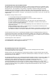
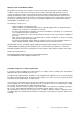
Pos Bild Abmessung [mm] Anzahl [Stück] 1370 x 914 1 870 x 1895 1 870 x 1895 1 654 x 1852 1 419 x 1895 1 419 x 1895 1 695 x 1852 1 685 x 1852 1 B556.01.0001 B556.01.0002 SWL B556.01.0018 SWR B556.01.0003 B556.01.0004 FWR B556.01.0005 FWL B556.01.0006 RW B556.01.
Pos Bild Abmessung [mm] Anzahl [Stück] 1280 x 868 1 550 x 1260 1 1240 x 410 1 18,5/29/375 2 30/30/375 2 18,5/29/519 2 19/24/615 28 14/58/1895 2 B556.01.0019 B556.01.0020 B548.03.0002 G556.01.0003 G556.01.0004 G548.01.00036 G548.01.0005 G556.01.
Pos Bild Abmessung [mm] Anzahl [Stück] 14/70/1895 2 18,5/18,5/1282 2 18,5/18,5/833 2 550 x 1895 1 10/27/35 2 G556.01.0002 G548.01.0045 G543.01.0043 K107.5518.
Pos Abmessung [mm] Bild Anzahl [Stück] 1 Copyright HRB 3662 20 10 m 1 5,0 x 80 3 4,5 x 70 8 4,0 x 60 20 4,0 x 50 20 3,5 x 35 30 3,0 x 30 80 Technische Änderungen vorbehalten
Pos Bild Copyright HRB 3662 21 Abmessung [mm] Anzahl [Stück] 3,5 x 15 20 1,6 x 30 20 120 x 40 2 200 x 240 1 4,5 x 70 2 130 x 170 1 3,9 x 25 4 Ø 12mm 4 Technische Änderungen vorbehalten
Pos Bild Abmessung [mm] Anzahl [Stück] 200 cm lang 1 1 1 1 1 Copyright HRB 3662 22 Technische Änderungen vorbehalten
Copyright HRB 3662 23 Technische Änderungen vorbehalten
Copyright HRB 3662 24 Technische Änderungen vorbehalten
Copyright HRB 3662 25 Technische Änderungen vorbehalten
Copyright HRB 3662 26 Technische Änderungen vorbehalten
Copyright HRB 3662 27 Technische Änderungen vorbehalten
Copyright HRB 3662 28 Technische Änderungen vorbehalten
Copyright HRB 3662 29 Technische Änderungen vorbehalten
Copyright HRB 3662 30 Technische Änderungen vorbehalten
Copyright HRB 3662 31 Technische Änderungen vorbehalten
Copyright HRB 3662 32 Technische Änderungen vorbehalten
Copyright HRB 3662 33 Technische Änderungen vorbehalten
- de - Netzanschluss 230VAC Steckdose Heizkreis 1 Wandelement SW-rechts Wandelement RW1 Heizkreis 2 Wandelement SW-links Wandelement RW2 Heizkreis 3 Bodenelement Dauerspannung 230VAC ( max.
- en - AC 230 V mains connection Socket Heating circuit 1 Wall element (right SW) Wall element RW1 Heating circuit 2 Wall element (left SW) Wall element RW2 Heating circuit 3 FSB2 floor element - Continuous voltage AC 230 V (max.
- fr - Raccordement secteur 230 VAC Prise Circuit de chauffage 1 Élément de paroi SW - droite Élément de paroi RW1 Circuit de chauffage 2 Élément de paroi SW – gauche Élément de paroi RW2 Circuit de chauffage 3 Élément de sol - Tension permanente 230 VAC (max.
- it Collegamento di rete 230 V CA Presa Circuito di riscaldamento 1 Elemento parete SW destra Elemento parete RW1 Circuito di riscaldamento 2 sinistra Elemento parete SW Elemento parete RW2 Circuito di riscaldamento 3 Elemento pavimento Tensione continua 230 V CA (max.
Copyright HRB 3662 38 Technische Änderungen vorbehalten
Copyright HRB 3662 39 Technische Änderungen vorbehalten
Copyright HRB 3662 40 Technische Änderungen vorbehalten
Copyright HRB 3662 41 Technische Änderungen vorbehalten
de Darstellung ohne Elektroteile en Representation without electrical parts fr schéma sans pièces électriques it Rappresentazione senza parti elettriche Copyright HRB 3662 42 Technische Änderungen vorbehalten
Copyright HRB 3662 43 Technische Änderungen vorbehalten
Copyright HRB 3662 44 Technische Änderungen vorbehalten
Copyright HRB 3662 45 Technische Änderungen vorbehalten
Copyright HRB 3662 46 Technische Änderungen vorbehalten
weka Holzbau GmbH, Johannesstr. 16 D-17034 Neubrandenburg Tel. : +49 (0)395 42908-0 Fax : +49 (0)395 42908-83 MA Art.-Nr.: 800.0286.22.05 T2-20.