BENCH GRINDER OWNER’S MANUAL WARNING: Read carefully and understand all ASSEMBLY AND OPERATION INSTRUCTIONS before operating. Failure to follow the safety rules and other basic safety precautions may result in serious personal injury.
Thank you very much for choosing a Wel-Bilt™ product! For future reference, please complete the owner’s record below: Model: _______________ Purchase Date: _______________ Save the receipt, warranty and these instructions. It is important that you read the entire manual to become familiar with this product before you begin using it. This machine is designed for certain applications only. The distributor cannot be responsible for issues arising from modification.
IMPORTANT SAFETY CONSIDERATIONS WORK AREA Keep work area clean, free of clutter and well lit. Cluttered and dark work areas can cause accidents. Do not use your tool where there is a risk of causing a fire or an explosion; e.g. in the presence of flammable liquids, gasses, or dust. Power tools create sparks, which may ignite the dust or fumes. Keep children and bystanders away while operating a power tool.
CHART FOR MINIMUM WIRE SIZE OF EXTENSION CORD: Nameplate AMPS CORD LENGTH 25ft. 50ft. 100ft. 150ft. 0-6 18 AWG 16 AWG 16 AWG 14 AWG 6-10 18 AWG 16 AWG 14 AWG 12 AWG 10-12 16 AWG 16 AWG 14 AWG 12 AWG 12-16 14 AWG 12 AWG (NOT RECOMMENDED) If in doubt, use larger cord. Be sure to check voltage requirements of the tool to your incoming power source. Do not expose power tools to rain or wet conditions. Water entering a power tool will increase the risk of electric shock.
Disconnect the plug from the power source before making any adjustments, changing accessories, or storing the tool. Such preventive safety measures reduce the risk of starting the tool accidentally. Use clamps or other practical way to secure and support the workpiece to a stable platform. Holding the work by hand or against your body is unstable and may lead to loss of control. Store idle tools out of reach of children and other untrained persons. Tools are dangerous in the hands of untrained users.
Do not overtighten spindle nuts. Adjust tool rests whenever necessary to maintain a distance of 1/8in. from the grinding wheel. ASSEMBLY: Mounting the Grinder to the Workbench Before attempting to use this grinder, it must be properly mounted to a workbench or grinding stand. WARNING! Bench grinders vibrate. Grinder movement during high-speed rotation may cause injury or damage to the workpiece or operator. Mount the grinder securely to a sturdy workbench or grinding stand. 1.
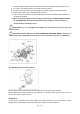
1. Mount the left and right shield rods to the inside of the wheel guards using hex bolts. 2. Once shield rods are firmly in place, slide the shield bracket onto the shield rod. 3. Tighten the carriage bolt, leaving it loose enough to allow the safety shield to be raised and lowered easily. NOTE: The eye shield should move freely when being adjusted, but stay in place when the locking knob is tightened. WARNING! Turn the power off and remove the plug from the outlet before changing the grinding wheels.
7. Wipe the flange surfaces clean, and install the new wheel, flange and the spindle hex nut. 8. To install a new grinding wheel, reverse the above procedure. 9. Be sure the grinding wheel and outer flange are properly seated on the spindle shaft. 10. Replace the wheel cover and reposition the tool rest. 11. The tool rest, spark deflector and eye shields will need to be readjusted after installation of the wheel is complete. 12.
1. Loosen, but do not remove, the two hex nuts holding the tool rest arm. 2. Slide the tool rest in or out to achieve a 1/8in. distance from the grinding wheel surface. 3. Re-tighten the two hex nuts. OPERATION: ON/OFF The rocker ON/OFF power switch is located on the front of the grinder. 1. Press the side marked ON to turn the grinder on. 2. Press the side marked OFF to turn the grinder off. Grinding Adjust the tool rest to accommodate large or unusually shaped workpieces.
coolant tray WORKLIGHT BULB REPLACEMENT When the light bulb is worn out and will no longer work, unfasten the screws that hold the lamp cover, and then gently remove the bulb from the holder by pushing ‘in’ and turning counterclockwise. Contact distributor for replacement bulbs. To replace, gently push the light bulb into the socket and turn clockwise, and then reattach the lamp cover by reversing the instructions provided above.
Machine operating. slows when 1. Feed rate too great. Wavy condition on surface of workpiece. 1. Machine vibrating. 2. Workpiece not being held firmly. 3. Wheel face uneven. 4. Wheel is too hard. Lines on workpiece. 1. Impurity on surface of wheel. 2. Workpiece not being held tightly. surface of 1. Reduce the rate at which the workpiece is fed into the working area of the tool (grinding wheel). 1. Ensure machine is securely mounted on a solid surface. 2.
DIAGRAM & PARTS LIST Page 12of 14
ITEM DESCRIPTIONS QTY. ITEM DESCRIPTIONS QTY. 1 Philips Screw (Zinc-plated) 14 35 Cord Clip 3 2 Philips Screw (Black) 6 36 Cord & Plug 1 3 Left Wheel Guard Cover 1 37 Cord Clip Fixed Plate 1 4 Hex Nut Type "I" (Zinc-plated) 1 38 Spring Washer (Black) 2 5 Wheel Flange 4 39 Hexagon Nut 4 6 36#Wheel,P200x25x15.
WARNING Some dust created by power sanding, sawing, grinding, drilling, and other construction activities contains chemicals known to the State of California to cause cancer, birth defects or other reproductive harm. Some examples of these chemicals are: • lead from lead-based paints, • crystalline silica from bricks and cement and other masonry products, and • arsenic and chromium from chemically-treated lumber. Your risk from these exposures varies, depending on how often you do this type of work.