WDRV-7464M/8464M Owner's Record The model and serial numbers are located at the rear. Record the serial number in the space provided below. Refer to these numbers whenever you call your dealer regarding this product. MODEL: WDRV-7444M WDRV-7464M WDRV-8444M WDRV-8464M WDRV-7474M Serial Number: Warnings To reduce the risk of electric shock do not remove cover (or back). NO user serviceable parts inside. Refer servicing to qualified service personnel.
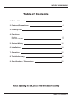
WDRV-7464M/8464M Table of Contents 1. Table of Contents 3 2. Features/Precautions 4 3. Packing List 7 4. Functions Monitor Remote Control 8 9 5. System Wiring 10 6. Installation 11 7. Operation 12 8. Troubleshooting 18 9. Specifications / Dimensions 20 Table of Contents.
WDRV-7464M/8464M Features ● WDRV-7464M/8464M is specifically designed as an automotive all round vision system.
WDRV-7464M/8464M ● ● ● ● ● ● ● Do not remove the cover To reduce the risk of electric shock and maintain the quality of the product, please do not remove the cover. Please follow the instructions of the wiring diagram in the Installation Guide. Keep small articles out of the reach of children Store small articles (screws, etc.) in places not accessible to children. If swallowed, consult physician immediately.
WDRV-7464M/8464M ● ● ● ● ● Caution Do not attempt to modify this product in any way without written authorization. Unauthorized modification could void the user's authority to operate this product. Power This set operates on DC power. The voltage is as indicated on the label on the back cover. Never apply AC power to the set directly. Do not allow anything to rest upon or roll over the power cord, and do not place the set where the power cord is subject to damage.
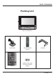
WDRV-7464M/8464M Packing List Set [TFT-LCD Monitor] Stand Bracket Manual Remote Controller (Option) Sunshield 2 Batteries (Type AAA) for Remote Controller (Option) Packing List .
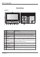
WDRV-7464M/8464M Functions MONITOR 1 2 NO 1 2 3 4 3 4 MENU LCD SPEAKER IR UP/DOWN , 5 SELECT 6 VOL 7 MENU 8 POWER/DIMMER 8. Function , 5 6 7 8 2 DESCRIPTION Video on the screen. Sound out 1W X 2 Max. Remote control sensor. (Remote control is optional) Use select items in the on screen menu, press UP/DOWN buttons to control front / rear view motorized camera only. Press select button to change video source and view mode.
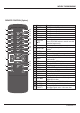
WDRV-7464M/8464M REMOTE CONTROL (Option) 1 RIGHT 2 3 4 5 SOURCE AUTO POWER QUAD OSD A/V INPUT SCAN SYSTEM A/V ON/OFF DISPLAY CA1 REAR CA2 LEFT CA3 CA4 DIMMER 6 10 11 12 13 14 15 16 17 18 19 20 21 7 MENU 22 23 24 8 EXIT 9 WIDE SELECT 25 SCAN-TIME TRIGGER PRIORITY No.
WDRV-7464M/8464M System Wiring [WDRV-7444M / 7464M [WDRV-8444M / 8464M Camera1 Camera2 Camera3 Camera4 MALE MALE [General Camera] 4Pin 4Pin 4Pin 4Pin 4Pin Trigger1 Signal Input Trigger2 Signal Input Trigger3 Signal Input Trigger4 Signal Input Trigger5 Signal Input FEMALE [Side View Camera] WDRV-3478C 6Pin WDRV-7444M/8444M 4Pin DC12V~32V GND FEMALE [Side View Camera] [Rear View Camera] [General Camera] WDRV-3478C WDRV-7063C WDRV-7464M/8464M 6Pin Video Out Audio Out Audio/ Video IN FEMALE MA
WDRV-7464M/8464M Installation ● Install the monitor on a surface which can width stand more weight than 5Kg (11 lbs) - Clean the surface before installation - Remove the protective paper covering the bottom of the bracket - Stick the provided bracket on the surface and fix it firmly with the screws. Mounting on the floor, console, etc. Mounting onto ceiling - Adjust the angle of the monitor and fasten the handle screws tightly. Installation .
WDRV-7464M/8464M Operation ● MENU MENU - Press to enter setup menu - Selectable OSD menu disappears within 5 seconds if there is no command given. - Menu Toggle Page1 (Menu) Page2 (Picture) - Use Page3 (Function) buttons to navigate menu, Page4 (OSD) SELECT EXIT adjust menu settings. * Different OSD depends on the Model. A. Press 'MENU' button on set. The following will appear on the screen. MENU AUTO SCAN OSD ASPECT TRIGGER.IN TRIGGER.TIME TRIGGER.
WDRV-7464M/8464M B. Press 'MENU' button twice times on set. The following will appear on the screen.
WDRV-7464M/8464M E. VIEW MODE.1 Single : CAM 1 ~ CAM 4 , A/V Dual (Half) : CAM 1 / CAM 2 , CAM 3 / CAM 4 CAM 1 or CAM 3 CAM 2 or CAM 4 Quad : CAM 1 / CAM 2 / CAM 3 / CAM4 CAM 1 CAM 2 CAM 3 CAM 4 Operation.
WDRV-7464M/8464M F. View Mode.2 (Tacho function : Option) Use the CAM2 only Off Mode Front View (CAM2) Power On : Below 10Km / h : Display on (CAM2) Above 10Km /h : Display Off Operation.
WDRV-7464M/8464M F-1. View Mode (Tacho function : Option) Use the CAM1,CAM2 Off Mode REAR View (CAM1) FRONT View (CAM2) Power On : Split Display REAR View (CAM1) Input from REAR TRIGGER Operation.
WDRV-7464M/8464M F-2. View Mode (Tacho function : Option) Use the CAM1,CAM2 (CAM3 ,CAM4) Off Mode REAR View (CAM1) FRONT View (CAM2) LEFT View (CAM3) RIGHT View (CAM4) Power On : Quad Display Front View (CAM2) Start : Below 10Km / h : CAM2 Display REAR View (CAM1) FRONT View (CAM2) LEFT View (CAM3) RIGHT View (CAM4) Above 10Km /h : Quad Display REAR View (CAM1) Input from LEFT,RIGHT,REAR TRIGGER Operation.
WDRV-7464M/8464M Troubleshooting Q: Screen is too bright. A: Adjust BRIGHTNESS or CONTRAST. When pressing RESET button, it will go back to default setting. SCREEN Q: Screen color is red or close to green. A: Adjust TINT in menu mode. Press preset to go back to default setting. Q: Colors are dim. A: Decrease the color by adjusting the button in menu mode. VIDEO Q: Screen is not clear. A: When the extension cable is too long diminishing of video may happen.
WDRV-7464M/8464M Q: Motorized camera does not operate. A: Check if motorized camera is connected with REAR. Check if source switches are in REAR mode. Q: Auto scan does not operate. A: Scan does not operate when there is only one camera image. Operation Error Q: Auto scan mode is too fast. A: Adjust S.TIME in appropriate level in menu mode. Q: OSD disappears in the screen. A: Set OSD [OFF] to [ON] in menu mode. Q: The screen does not change when entering trigger. A: Set INPUT [Auto] in menu mode.
WDRV-7464M/8464M Specifications TYPE SCREEN SIZE BRIGHTNESS LCD VISUAL FIELD (ANGLE) CONTRAST MTBF INPUT SIGNAL FEATURE POWER CONSUMPTION SIZE(Width x Depth x Height) POWER SOURCE WORKING TEMPERATURE STORAGE 7 Inch Series 8 Inch Series TFT-LCD COLOR 7 Inch 8 Inch 500 450 65 65 70 70 50 60 50 70 500 500 10,000 20,000 COMPOSITE (75Ω) 10.2W 9.6W 7.7 x 1.3 x 5.7 inch 8.5 x 1.3 x 6.3 inch DC +12V ~ +32V 20 70 4 30 80 Dimensions 8.5" 7.7" 5.7" 6.3" 1.3" 1.3" 1.3" 1.