WHA 3000P Hot Air Station Operating Instructions Version 2.3 Weller Tools GmbH Carl-Benz-Str.
Table of contents Page 1. Description Technical data 5 5 2. Placing in operation 2.1 Manual operating mode 2.2 Automatic operating mode 2.3 Setting temperature profile 2.4 Starting program 2.5 Control of the vacuum function 2.6 Saving and loading temperature-time profiles 6 6 7 8 8 9 9 3. External sensor 3.1 External sensor with measuring function "MEASURE MODE“ (factory setting) 3.2 Teach In Mode procedure 3.3 External sensor with control function "CONTROL MODE“ 10 10 10 10 4. Lock Mode 11 5.
Operating instructions WHA 3000P Front view WHA3000P 1 2 3 4 5 6 7 8 9 10 11 12 13 14 LCD Display "UP" Control Key "DOWN" Control Key Mains Switch "TIME"/"PREHEAT" Control Key (time setting auto.
Rear view WHA3000P 15 16 17 18 19 20 21 22 Vacuum Pump Filter Hand-piece Connecting Hose Stand Switch Connection Mains Connection Mains Fuse Connection for Manual Control Console; Foot Switch PC Interface, RS232 Connection for WHP3000 (bottom heater), RS232 Interface Page 4 of 14
We thank you for the confidence you have shown by purchasing the Weller WHA 3000P Hot Air Station. During manufacturing, the strictest quality requirements are applied; these assure the correct function of the device and make it possible to obtain optimal soldering results. Warning! Prior to placing the device in operation, please carefully read these operating instructions and the safety instructions enclosed. If the safety instructions are not observed, there is a risk of injury.
Technical data Dimensions (W X L X H): Mains voltage: Power consumption: Air flow rate: Temperature range: Accuracy: Vacuum: Mains fuse: Protection class: 240 (9.44) X 270 (10.63) X 170 (6.69) mm (inch) 230 V (120 V) AC 600 W 5 – 50 l/min 50°C –550°C (150°F – 999°F) +/- 30°C (+/- 54°F) - 0.6 bar 230 V / T6.3A (120 V / T8 A) 1 (Control Unit and Hand-Piece are hard grounded) 2. Placing in operation Place the hand-piece, with the hot air nozzle installed, in the AKT30 safety stand.
2-Position Foot Switch (20): Hot air-Position 1, Vacuum-Position 2 (hot air and vacuum are only active in the Manual Mode, when the Foot Switch is depressed) Manual Control Console (20): (Optional) Hot Air "AIR“ Control Key, Vacuum "VAC“ Control Key When the hand-piece is placed in the AKT30 Safety Stand (17), the hot air is switched off by a Mirco Switch.
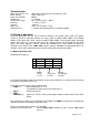
Information on the display (1) TEMP 210°C 300°C 210°C Nozzle Pre-Heater Nozzle AIR 40 l 25 l 30 l TIME 100s 50s 15s step 1 step 2 step 3 Nozzle or bottom heater symbol Temperature of the nozzle or bottom heater (with WHP 3000) Air flow rate in l/min Time remaining for the temperature profile step in sec. 2.
2.4 Starting program The soldering process and thus the 3-step temperature-time profile is started: Directly on the Control Panel: START/STOP (10) Control Key, LED (9) illuminates.
PROGRAM 1 E X I T L O A D UP PRESS AT THE SAME TIME S A V E DOWN The program memories 1 - 10 can be selected using the UP/DOWN Control Keys (2)/(3). The preferred program can be selected by pressing the LOAD Control Key (6). The indication on the display changes to the automatic mode and displays the selected parameters. If a temperature-profile has been prepared, it can be saved in the selected program memory by pressing the SAVE Control Key (5).
3.2 Teach In Mode procedure During the sequence of an automatic temperature-time profile, it is possible to continue switching the process stages 1-3 manually by pressing the Control Key "TIME" / "PREHEAT" (5). If the external sensor is suitably positioned on the assembly or component, its temperature can be monitored during the entire process sequence and can be continued to be switched when the desired specified temperatures (stage 1-3) have been reached.
Nozzle change Caution: Risk of burns! The hot air nozzle remains hot for some time after power off or removal. The hot air nozzles are fastened to the heating element using a clamping screw. To change the nozzle, loosen the screw and remove the hot gas nozzle using the Nozzle Change Tool provided. 8. Maintenance The vacuum filter (15) is soiled by flux residues and contaminants and must be replaced if the vacuum drops. 9.
12.
13.