Wells-Gardner Electronics Corporation Service Manual for D9300 Series Digital-Control Color Monitor Wells-Gardner Electronics 5500W.
Wells-Gardner Electronics Corporation INDEX 1. SAFETY PRECAUTION……………………………… 1 2. SPECIFICATION……………………………………… 2 3. TECHNCIAL FEATURES……………………………. 3 4. TIMING CHART………………………………………. 4 5. SET UP………………………………………………….. 6 6. CONTROLS AND ADJUSTMENT…………………... 7 7. ADJUSTMENT SPECIFICATION…………………… 12 8. DESCRIPTION OF CIRCUIT OPERATION………...17 9. TROUBLE SHOOTING………………………………..
Wells-Gardner Electronics Corporation 1. SAFETY PRECAUTION: WARNING: Service should not be attempted by anyone unfamiliar with the necessary precautions on this unit. The following precautions are necessary during servicing. 1-1 Some parts, such as a picture tube in this unit, have special safety-related characteristics for X-RAY RADIATION protection. For continued safety, the parts replacement should be undertaken referring to below article (1-2 and 1-5).
Wells-Gardner Electronics Corporation 2. SPECIFICATION: 2-1 Picture Tube. x Size: 18V x Dot Pitch: .25mm 2-2 Signal Input. x Video Input: Analog, Positive Signal (0.7V p-p) x Horizontal Sync: TTL Level, Positive or Negative Pulse x Scanning : 28 KHz-70KHz x Vertical Input: TTL Level, Positive or Negative pulse x Scanning : 40-160Hz 2-3 Power Supply. x Power Input : 120-240 VAC, 50/60Hz x Fuse Rating: 250V, 3.
Wells-Gardner Electronics Corporation 3. TECHNICAL FEATURES: 3-1 Microprocessor control with OSD (On screen display menu). Microprocessor recognizes the input computer signal and signal output from the customer control board connected to the main board by a flat cable. 3-2 Universal AC Input Voltage. Power supply operates on 120-240 VAC at 60/50Hz for use all over the world. 3-3. Protection Circuit for over-current.
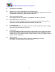
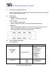
Wells-Gardner Electronics Corporation 4. TIMING CHART: Factory Pre-Set Timing Modes. Horizontal and Vertical Timing Diagram for Table 1 . TABLE 1 : QUANTUM 801GX FORMAT DESCRIPTION H V FH A B C D E POL. FV A B C D E POL. VIDEO MVP-NSW US500 MK6 VGA_M4 MODE 1 640*400 29.63Hz 33.75µs 1.76µs 3.52µs 26.67µs 1.86µs POSITIVE 62.91Hz 15.88ms 0.0338ms 1.680ms 13.56ms 0.675ms POSITIVE ANALOG MODE 2 640*400 31.5KHz 31.778µs 3.88µs 1.84µs 25.4µs 0.63µs POSITIVE 70.1Hz 14.2ms 0.0636ms 1.110ms 12.7ms 0.
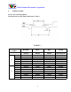
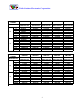
Wells-Gardner Electronics Corporation QUANTUM 801GX FORMAT DESCRIPTION H V FH A B C D E POL. FV A B C D E POL. VIDEO QUANTUM 801GX FORMAT DESCRIPTION H V FH A B C D E POL. FV A B C D E POL. VIDEO VG900602 DMT8075 VS900603 VG901101 VG901101 MODE 5, S-VGA VESA 680*480 37.500KHz 26.667us 2.032us 3.810us 20.317us 0.508us NEGETIVE 75.00Hz 13.333ms 0.080ms .427ms 12.800ms 0.027ms NEGETIVE ANALOG MODE 6 VGA 800*600 37.879KHz 26.400µs 3.200µs 2.200µs 20.000µs 1.000µs POSITIVE 60.317Hz 16.579ms 0.
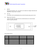
Wells-Gardner Electronics Corporation 5. SET UP: Setting up your monitor is easy. All you have to do is make a few simple connections and adjustments. The procedure is as follows: 5.1 Start Up. Your monitor starts up automatically when you insert the power plug to power source. 5-2. Single Cable Connection. Connect the 15pin signal cable to the source and lock both screws to ensure that the monitor is properly grounded. D type 15pin connector: PIN NO.
Wells-Gardner Electronics Corporation 6. CONTROLS AND ADJUSTMENTS: There are four switches on the control panel. Adjustable controls allow the best display status for individual requirements. 6-1. Key Function. 1. MODE/EXIT MODE – Call the Main-Menu OSD 2. SEL / Degauss SEL – Call the Sub-Menu OSD Degauss – Degausses the CRT (active when the OSD is not displayed) 3. DOWN/UP When the Main-Menu is displayed, you can select each function using these keys.
Wells-Gardner Electronics Corporation 6-3. OSD Controls - User’s control. A. 1) 2) 3) 4) 5) 6) 7) BRIGHTNESS ADJUSTMENT. Press the “MODE” key then Main-Menu OSD comes out as figure on next page. Search “BRIGHTNESS” sub-menu using “UP/DOWN” key on the Main-Menu OSD. Select the “BRIGHTNESS” by pressing “SEL” key. The “BRIGHTNESS” OSD color changes from yellow to red. Adjust Brightness as much as you want using “UP/DOWN” key. After finishing the Brightness adjust, press the “MODE” key.
Wells-Gardner Electronics Corporation A. BRIGHTNESS ADJUSTMENT B. C. D. E. F. G. H. I. J. CONTRAST H. POSITION H. SIZE V. POSITION V.
Wells-Gardner Electronics Corporation 6-3 OSD Controls (continued): K. COLOR ADJUSTMENT 1) Press the “MODE” to show the Main-Menu OSD as shown by the left-below figure. 2) Search the “COLOR” sub-menu using “UP/DOWN” key on the Main-Menu OSD. 3) SELECT the “COLOR” by pressing “SEL” key. The color Sub-Menu OSD appears as shown by the right-below figure. 4) Search “USER” using “UP/DOWN” key. (“COLOR1” and “COLOR2” are adjusted in factory by auto-alignment machine.
Wells-Gardner Electronics Corporation L. RECALL. When the “RECALL” key is pressed, all user’s adjustment values are changed to the factory values. M. LANGUAGE. The menu is available in four languages. 1. Press the “MODE” key and the Main-Menu OSD will appear as in the previous figure. 2. Search the “LANGUAGE” sub-menu using the “UP/DOWN” key on the Main-Menu OSD. 3. Select the “LANGUAGE” by pressing the “SEL” key. Then the Language sub-menu will appear as in the following figure 4.
Wells-Gardner Electronics Corporation 7. ADJUSTMENT SPECIFICATION: 7-1. Adjustment Sequence: The monitor requires a min. of 15 minutes warm up time before adjustment. 7-2. Adjustment Sequence: FBT B+ Voltage → G2 Voltage → Hor. Center → Hor. Size → Hor. Position → Ver. Size → Ver. Position → Side-pin → Trapezoid → Focus → White Balance → Convergence (if needed). 7-3. Adjustment Procedure - How to enter the Factory Mode: Press Menu and Down simultaneously and hold down for three seconds.
Wells-Gardner Electronics Corporation 7-3.5 Purity and Convergence Adjustment. (If Required) A. Purity Adjustment. 1. Demagnetize the picture tube and cabinet using a degaussing coil. 2. Turn the CONTRAST and BRIGHTNESS controls to maximum. 3. In User Color Menu, adjust RED and BLUE controls to provide only a green raster. 4. Loosen the clamp screw holding the yoke and slide the yoke backward to provide vertical green belt (zone) in the picture screen. 5. Remote the Rubber wedges 6.
Wells-Gardner Electronics Corporation 7-3.6 White Balance adjustment (video). 1. Warm up the unit for 15 minutes 2. Input the window pattern with 31KHz 640*480 mode. 3. Adjust the color temperature to be X=0.285+/-0.015 and Y=0.293+/-0.015 by R.G.B. gain on User Color Menu or User Preference. 7-4 OSD FACTORY CONTROL This should be adjusted by a technician or qualified repair personnel. This monitor has two-adjustment modes. One is for the user’s own adjustment and other is for factory adjustment.
Wells-Gardner Electronics Corporation B. Exit and save. (Save is automatic) 1. After finishing adjustments, select “RECALL” using “UP/DOWN” key. 2. Press “SEL” key until OSD disappears. The adjusted value is saved and exits from the factory mode. C. Adjustment. All adjustment methods are same as user’s control mode except “COLOR” 7-5 White balance Adjustment: A. Pre-adjustment. 1. Warm up monitor for 15 minutes. 2. Input the small window pattern with 31KHz 640*480 mode. 3.
Wells-Gardner Electronics Corporation 7-5 B.
Wells-Gardner Electronics Corporation 8.DESCRIPTION OF CIRCUIT OPERATION: 8-1. Mode Control. 8-1.1 H-Sync is inputted to pin 30 of IC601, V-Sync to pin 29 of IC601 for each mode and pin 27, 26 of IC601 output always positive polarity sync. 8-1.2 The outputs from IC601 are as below (See table below) No. Frequency Range of Frequency OUTPUT (MCU PIN) (CS3) (CS2) (CS1) OFF ST-BY SUS-P LED Hf Vf Resolution Hf (KHz) Vf (Hz) 38 39 40 5 3 4 6 KHz Hz 1 31 70 720x400 28 ~32.
Wells-Gardner Electronics Corporation 8-2 Deflection Processor (IC301): 8-2.1 Horizontal section. 8-2.1.2 Horizontal Oscillation. Horizontal free frequency is set to 48KHz by R314 and C347. Auto-sync processing can be done from 28KHz to 70KHz by means of IC301 without any adjustment. 8-2.1.3 Phase Shift. Horizontal phase shift is controlled by IC601 using I²C BUS control. 8-2.1.4 Horizontal driver output.
Wells-Gardner Electronics Corporation 8-2.2.4 East-west parabola. A parabola wave-form is available on pin 24 of IC301 for driving the pincushion correction stage. Amplitude of parabola waveform is controlled by IC601 using I²C. 8-2.3 B+ Regulator. B+ PWM regulator output is available on pin 28 of IC301 for driving the B+ control stage. This PWM output is adjusted through VR301. 8.3 Vertical Deflection (IC201): IC201 (KA2142) is used for direct driving of the vertical deflection yoke.
Wells-Gardner Electronics Corporation Q317, Q318 are off when horizontal frequency is 53KHz a 61KHz Q316, Q317, Q318 is off when horizontal frequency is 62KHz a70KHz 8-6 FBT (Flyback Transformer): The high voltage for CRT anode focus, G2 voltage for CRT and – 12V for vertical deflection are generated by the FBT. Also, -130V for G1 voltage, horizontal flyback pulse, +128V video supply, and for dual focus units 800V dynamic focus supply.
Wells-Gardner Electronics Corporation 9. TROUBLESHOOTING: 9-1. NO POWER.
Wells-Gardner Electronics Corporation 9-2. NO VIDEO.
Wells-Gardner Electronics Corporation 9-3.
Wells-Gardner Electronics Corporation 9-4 TROUBLE IN HORIZONTAL SIZE: 24
Wells-Gardner Electronics Corporation 9-5.
Wells-Gardner Electronics Corporation 9-6.