Installation Manual IM 1029-2 Group: Chiller Part Number: 331374611 Effective: January 2013 Supersedes: October 2012 Magnitude™ Magnetic Bearing Centrifugal Chillers Model WMC-145SBS to 400DBS HFC-134a 50/60 Hertz 00
Table of Contents Electrical Data ............................................. 31 VFD Line Harmonics ................................... 43 Fuses ............................................................ 44 Introduction ........................................... 3 Nomenclature ................................................. 3 Installation ............................................. 4 System Pumps ..................................... 44 Receiving and Handling .................................
Introduction General Description The Daikin Magnitude™ Frictionless Centrifugal Chillers are complete, self-contained, automatically controlled, fluid-chilling units featuring oil-free, magnetic bearing compressors. Each unit is completely assembled and factory tested before shipment. They are designed for indoor, non-freezing installation only. Magnitude chillers are equipped with two compressors operating in parallel with a single evaporator and single condenser.
Installation Receiving and Handling The unit should be inspected immediately after receipt for possible damage. All Daikin centrifugal water chillers are shipped FOB factory and all claims for handling and shipping damage are the responsibility of the consignee. On units with factory-installed insulation, the insulation is removed from the vessel lifting hole (also used for transportation tie-downs) locations and are shipped loose. They should be secured in place after the unit is finally placed.
Location and Mounting Location WMC chillers are intended only for installation in an indoor or weather protected area consistent with the NEMA 1 rating on the chiller, controls, and electrical panels. Equipment room temperature for operating and standby conditions is 40°F to 104°F (4.4°C to 40°C). Clearance The unit must be mounted on a level concrete or steel base and must be located to provide service clearance at one end of the unit for possible removal of evaporator and/or condenser tubes.
size and type required. Victaulic connections are AWWA C-606 on 14-inch and larger sizes. Field supply transitions if Victaulic brand AGS® (Advanced Groove System) type grooves are used on the field piping. ! CAUTION Freeze Notice: Neither the evaporator nor the condenser is self-draining; both must be blown out to help avoid damage from freezing temperatures. The piping should include thermometers at the inlet and outlet connections and air vents at the high points.
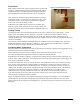
Flow Switch Note: Chiller units must have flow switches for the evaporator and condenser. Daikin furnishes factory-installed and wired, thermaltype flow switches as standard equipment on Magnitude chillers. Field-installed and wired Delta-P switches can be used instead. Figure 2, Unit-Mounted Flow Switch They prevent the unit from starting without sufficient water flow through the vessels.
Figure 4, Tower Bypass, Cold Weather Operation Figure 3, Tower Bypass, Mild Weather Operation ≈ ≈ ≈ ≈ ! CAUTION Tower water treatment is essential for continued efficient and reliable unit operation. If not available in-house, competent water treatment specialists should be contracted. Field Insulation If the optional factory-installation of thermal insulation is not ordered, insulation should be field installed to reduce heat loss and prevent condensation from forming.
Physical Data and Weights With positive pressure systems, the pressure variance with temperature is always predictable, and the vessel design and pressure relief protection are based upon pure refrigerant characteristics. R-134a requires ASME vessel design, inspection and testing and uses spring-loaded pressure relief valves. When an over-pressure condition occurs, spring-loaded relief valves purge only that quantity of refrigerant required to reduce the pressure to the valve’s set pressure and then close.
Mounting/Lifting/Total Weights Drawings are for reference only and are not indicative of all unit configurations. "LL" "LW" OH RB X Z LB MFW LF MFL RF OL OW 332834901 DRAWINGNUMBER 10 Magnitude™ Frictionless Centrifugal Chillers – Model WMC 00 REV.
Chiller Dimensions Figure 5, WMC IM 1029-2 145D, 2 Pass (See page 17 for notes.
Figure 6, WMC 12 145S, 2 Pass (See page 17 for notes.
Figure 7, WMC IM 1029-2 150D, 2-Pass (See page 17 for notes.
Figure 8, WMC 14 250D, 2-Pass (See page 17 for notes.
Figure 9, WMC IM 1029-2 290D, 2-Pass (See page 17 for notes.
Figure 10, WMC 16 400D, 2-Pass (See page 17 for notes.
Drawing Notes NOTES: 1. All dimensions are in inches and [millimeters] unless noted otherwise. 2. Final connections must allow for +/- 0.5 inch [12.7mm] manufacturing tolerances. 3. 1.00-inch FPT [25.4 mm] evaporator and condenser relief valves must be piped per ANSI / ASHRAE 15. Number of relief valves is 1 per evaporator and 2 per condenser. 4. 0.375 inch [9 mm] suction nozzle relief valve (dual compressor units only) must be piped per ANSI / ASHRAE 15. 5. Minimum clearances are shown below.
Pressure Drop Curves NOTE: The Evaporator and Condenser Model Codes are shown on page 9. The -B and -C designations shown on the curves refer to vessel tube count, which is determined by the computer selection program.
Figure 13, 2-Pass Evaporators WMC Evap - Water Side Pressure Drop (2 pass) 60 E2212-B E2212-C E2212-D 50 E2209-B E2209-C E2209-D 40 EPD - ft E2612-B E2609-B E3012-B 30 E3012-C 20 10 0 0 500 1000 1500 2000 EGPM - gpm Figure 14, 2-Pass Condensers WMC Cond - Water Side Pressure Drop (2 pass) 35.0 C2012-B C2012-C 30.0 C2009-B C2009-C 25.0 C2212-B CPD - ft C2212-C C2209-B 20.0 C2209-C C2612-B 15.0 C2612-C 10.0 5.0 0.
Figure 15, 3-Pass Evaporators WMC Evap - Water Side Pressure Drop (3 pass) 90 E2212-C E2212-D 80 E2209-C E2209-D 70 E2612-B E2609-B EPD - ft 60 E3012-C 50 40 30 20 10 0 0 200 400 600 800 1000 1200 EGPM - gpm Figure 16, 3-Pass Condensers WMC Cond - Water Side Pressure Drop (3 pass) 60.0 C2012-C C2009-C 50.0 C2212-C C2209-C CPD - ft 40.0 C2612-C 30.0 20.0 10.0 0.
Relief Valves As a safety precaution and to meet code requirements, each chiller is equipped with pressure relief valves located on the condenser and evaporator for the purpose of relieving excessive refrigerant pressure (caused by equipment malfunction, fire, etc.) to the atmosphere. Most codes require that relief valves be vented to the outside of a building and this is a desirable practice for all installations. Relief piping connections to the relief valves must have flexible connectors.
Sizing Vent Piping (ASHRAE Method) Relief valve pipe sizing is based on the discharge capacity for the given evaporator or condenser and the length of piping to be run. Discharge capacity for R-134a vessels is calculated using a complicated equation that accounts for equivalent length of pipe, valve capacity, Moody friction factor, pipe ID, outlet pressure and back pressure. The formula and tables are contained in ASHRAE Standard 15-2001.
Electrical Information Wiring, fuse and wire size must be in accordance with the National Electric Code (NEC). Important: The voltage to these units must be within ±10% of nameplate voltage, and the voltage unbalance between phases must not exceed 2%. Since a 2% voltage unbalance will cause a current unbalance of 6 to 10 times the voltage unbalance per NEMA MG-1, 1998 Standard, it is most important that the unbalance between phases be kept at a minimum.
Case 2, WMC 145D – 400D Field Power Wiring Case 2 adds optional factory-mounted and wired EMI filters. The actual field wiring is the same as Case 1. Figure 19, Case 2 Field Power Wiring NOTES: 1. Optional EMI Filter 2. Remove standard line reactor when optional combination line reactor/harmonic filter assembly is used. 3. Circuit breakers shown in the diagram function exclusively as disconnect switches.
Case 3, WMC 250D, 290D, 400D Field Power Wiring Case 3 adds the combo harmonic filters. The standard line reactors are shipped in the unit and are removed and discarded in the field. Field wiring to the harmonic filter would be the same size as the incoming lines. Figure 20 shows the optional multi-point connection to two disconnect switches. The standard would be a single-point connection to a single disconnect switch. Figure 20, Case 3 Field Power Wiring NOTES: 1. Not applicable 2.
Case 4, WMC 250D, 290D, 400D Field Power Wiring Case 4 adds both the EMI filters and the combo harmonic filters. The EMI is factory mounted and the line side of the EMI is factory wired, the load side is field wired to the remotely mounted harmonic filter. The standard line reactors are shipped in the unit and are removed and discarded in the field. The field wiring size to and from the harmonic filter should be the same as the incoming lines.
Case 5, WMC 145D – 150D Field Power Wiring Case 5 adds remote-mounted combo harmonic filters. In these model WMCs the fuses are located in the compressor. Field wiring is run from the disconnect switch load side to the power block in the remote filter. The standard line reactors are shipped in the unit and are removed and discarded in the field. A shipped loose power block is field mounted in their former location and one side is wired to the remote filter.
Case 6, WMC 145D – 150D Field Power Wiring Refer to Case 5. Case 6 merely adds factory-mounted EMIs to the load side of the circuit breaker. The EMI load side is wired out to the harmonic filter. In other words, the EMI is interposed between the breaker and the filter Figure 23, WMC 145D, 150D Case 6 Field Power Wiring NOTES: 1. Optional EMI Filter 2. Remove standard line reactor when optional combination line reactor/harmonic filter assembly is used. 3.
Figure 24, Case 8 WMC 145S Field Power Wiring NOTES: 1. Not applicable 2. Remove standard line reactor when optional combination line reactor/harmonic filter assembly is used. 3. Circuit breakers shown in the diagram function exclusively as disconnect switches. Case 9 WMC 145S Field Power Wiring Case 9 adds a factory-mounted EMI to the remote-mounted harmonic filter.
Optional Harmonic Filter The optional harmonic filters are field mounted and wired option, wired from the chiller power panel circuit breakers out to the filter and back to the chiller’s power fuses and contactors. They limit current distortion to less than 7% and meet IEEE 519 standards chiller power factor is improved across the entire load range. The filters are mounted in a UL Type 1 enclosure and are UL and cUL listed. Model HG60 is wall mounted, the balance are floor mounted.
Electrical Data General Note: The RLA for use in the following tables is obtained by the selection of a specific unit by Daikin. When shipped, a unit will bear the specific RLA, stamped on the nameplate, for the selected operating conditions. ! CAUTION The RLA stamped on the unit may be lower than the minimum shown in the following tables, in which case the minimum table value must be used for wire sizing.
Table 9, WMC 145S-B, 3/50/400 SINGLE POINT CONNECTION, STANDARD COMPRESSOR CHILLER RLA [Amp] LRA [Amp] QTY MCA [Amp] MOP [Amp] Disc.
Table 12, WMC 145D-B & WMC 150D-B, 3/60/460 (Continued) MULTI-POINT CONNECTION, OPTIONAL COMPRESSOR (EACH) RLA [Amp] LRA [Amp] QTY MCA [Amp] 52 53 - 55 56 - 65 68 69 - 77 78 - 80 81 - 85 90 - 92 93 - 99 100 - 104 105 - 111 112 - 113 72 72 72 94 94 94 94 124 124 124 124 124 2 2 2 2 2 2 2 2 2 2 2 2 65 67 - 69 70 - 82 85 87 - 97 98 - 100 102 - 107 113 - 115 117 - 124 125 - 130 132 - 139 140 - 142 CHILLER (PER CIRCUIT) DISC. POWER MOP SWT.
Table 14, WMC 145D-B & WMC 150D-B, 3/50/400 SINGLE POINT CONNECTION, STANDARD COMPRESSOR (EACH) CHILLER POWER DISC. BLOCK SWT.
WMC 250D & 290D, Dual Compressor Table 15, WMC 250D-B & WMC 290D-B, 3/60/460 SINGLE POINT CONNECTION, STANDARD COMPRESSOR (Each) CHILLER DISC. POWER SWT.
Table 16, WMC 250D-B & WMC 290D-B, 3/50/400 SINGLE POINT CONNECTION, STANDARD COMPRESSOR (EACH) CHILLER DISC. POWER SWT.
Table 17, WMC 250D-B & WMC 290D-B, 3/50/380 SINGLE POINT CONNECTION, STANDARD COMPRESSOR (EACH) CHILLER DISC. POWER SWT.
WMC 400D 3/60/460 ONLY Table 18, WMC 400D-B, 3/60/460 SINGLE POINT CONNECTION, STANDARD COMPRESSOR (EACH) RLA [Amp] LRA [Amp] 118 – 123 124 - 125 126 127 to 137 138 139 to 148 149 to 153 176 176 176 176 176 154 to 160 CHILLER DISC. POWER SWT.
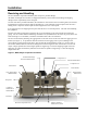
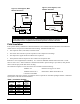
Figure 25, Power Panel (Front End Box) Power Cable Entrance Access Plate on Top Transformers T2, T3, T4 Current Transformer Power Connection Disconnect switch w/Lockout, Ground Fault Relay Disconnect Switch w/ Thru-the-Door Handle Disconnect switch w/Lockout, Comp #2 Transformer T1 Power System Filter EMI Comp #2 Power System Filter EMI Comp #1 Control Power Interrupt Relay (4) Control Power Fuses Drive Reactor Comp #1 IM 1029-2 Drive Reactor Comp #2 Magnitude™ Frictionless Centrifugal Chillers
Figure 26, Control Panel EXV Board Field Wiring Knockouts Terminal Board TB UTB1 for Field Wiring Connections On/Off Switches UNIT COMP #1 COMP #2 Controller OITS PC Universal Communication Module Comp #1 I/O 40 Magnitude™ Frictionless Centrifugal Chillers – Model WMC Comp #2 I/O IM 1029-2
Figure 27, Field Control Wiring Diagram NOTE: Complete notes are on the following page.
Field Wiring Diagram Notes 1. Compressor front end box is factory mounted and wired. All line side wiring must be wired in accordance with the nec and be made with copper wire and copper lugs only. Use only copper supply wires with ampacity based on 75°C conductor rating. Main power wiring between the front end box and compressor terminals is factory installed. • Minimum wire size for 115 VAC is 12 ga. for a maximum length of 50 feet.
Control Wiring The control circuit on the Daikin centrifugal packaged chiller is designed for 115-volts. Control power is supplied from a factory-wired transformer located in the electrical box. VFD Line Harmonics Despite their many benefits, care must be taken when applying VFDs due to the effect of line harmonics on the building electric system. VFDs cause distortion of the AC line because they are nonlinear loads, that is, they don't draw sinusoidal current from the line.
EMI Radiated EMI is similar to an unwanted radio broadcast being emitted from the power lines. There are many pieces of equipment that can generate EMI, variable frequency drives included. In the case of variable frequency drives, the electrical noise produced is primarily contained in the switching edges of the pulse width modulation (PWM) controller. As the technology of drives evolves, switching frequencies increase.
Multiple Chiller Setup WMC units have their control components factory wired to an internal network (LAN) so that the components can communicate with each other, within the chiller itself.
MicroTech II Operator Interface Touch Screen (OITS) Settings Settings for any type of linked multiple compressor operation must be made to the MicroTech II controller. Settings on a dual compressor unit are made in the factory prior to shipment, and verified in the field before startup.
Prestart System Checklist Yes No N/A Water system filled, vented ...................................................................... Pumps installed, (rotation checked), strainers cleaned ............................. Controls (3-way, face and bypass dampers, bypass valves, etc.) operable Strainer installed at evaporator inlet .........................................................
Long Term Storage This information applies to new units being stored waiting for startup or to existing units that may be inoperative for an extended period of time. The chiller must be stored in a dry location indoors and protected from any damage or sources of corrosion. A Daikin service representative must perform an inspection and leak test of the unit on minimum quarterly schedule, to be paid by the owner or contractor.
Operation Operator Responsibilities It is important that the operator become familiar with the equipment and the system before attempting operation. During the initial startup of the chiller, the Daikin technician will be available to answer any questions and instruct in the proper operating procedures. It is recommended that the operator maintain an operating log for each individual chiller unit. In addition, a separate maintenance log should be kept of the periodic maintenance and servicing activities.
Since there are many other factors that can influence performance, systems may successfully operate below these suggestions. However, as the water volume decreases below these suggestions, the possibility of problems increases. Variable Speed Pumping Variable water flow involves inversely changing the water flow through the evaporator as the load changes.
Transfer Back to Grid Power: Proper transfer from stand-by generator power back to grid power is essential to avoid compressor damage. ! WARNING Stop the chiller before transferring supply power from the generator back to the utility power grid. Transferring power while the chiller is running can cause severe compressor damage. The procedure for reconnecting power from the generator back to the utility grid is shown below.
Connection to Chiller Connection to the chiller for all BAS protocols will be at the unit controller. An interface card, depending on the protocol being used, will have been factory installed in the unit controller if so ordered, or it can be field installed.
IM 1029-2 Magnitude™ Frictionless Centrifugal Chillers – Model WMC 53
Daikin Learning Institute Now that you have made an investment in modern, efficient Daikin equipment, its care should be a high priority. For training information on all Daikin HVAC products, please visit us at www.DaikinApplied.com /Training, or call 540-248-9646 to speak to the Training Department. Warranty All Daikin equipment is sold pursuant to Daikin standard terms and conditions of sale, including Limited Product Warranty. Consult your local Daikin Representative for warranty details.