531 OWNERS MANUAL MODEL WVSW VENTLESS HOOD For CONVEYOR WARMERS Includes INSTALLATION USE & CARE SERVICE IMPORTANT: DO NOT DISCARD THIS MANUAL This manual is considered to be part of the appliance and is to be given to the OWNER or MANAGER of the restaurant, or to the person responsible for TRAINING OPERATORS of this appliance. Additional manuals are available from your WELLS DEALER. THIS MANUAL MUST BE READ AND UNDERSTOOD BY ALL PERSONS USING OR INSTALLING THIS APPLIANCE.
LIMITED WARRANTY STATEMENT Unless otherwise specified, all commercial cooking equipment manufactured by WELLS MFG. CO. is warranted against defects in materials and workmanship for a period of one year from the date of original installation or 18 months from the date of shipment from our factory, whichever comes first, and is for the benefit of the original purchaser only.
TABLE OF CONTENTS WARRANTY SPECIFICATIONS FEATURES & OPERATING CONTROLS AGENCY LISTING INFORMATION PRECAUTIONS & GENERAL INFORMATION INSTALLATION OPERATION CLEANING INSTRUCTIONS TROUBLESHOOTING SUGGESTIONS SERVICE INSTRUCTIONS PARTS & SERVICE CUSTOMER SERVICE DATA xi 1 2 3 4 5 7 8 9 10 11 11 INTRODUCTION Thank You for purchasing this Wells Manufacturing Co. appliance.
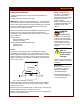
FEATURES & OPERATING CONTROLS WVSW VENTLESS HOOD Fig.
FEATURES & OPERATING CONTROLS (continued) ITEM DESCRIPTION CANOPY Removable canopies aid in vapor capture at entry and exit of the conveyor warmer. Canopies hang from mounting pins at each end of the hood. ELECTRICAL The hood plugs into a NEMA 5-15R (120V) or 6-15R (208/240V) receptacle with a 6' power cord. An illuminated power switch on the front panel is used to start/stop the hood fan. EXHAUST The hood uses an exhaust fan to provide air movement.
PRECAUTIONS AND GENERAL INFORMATION WARNING: Electric Shock hazard All servicing requiring access to non-insulated electrical components must be performed by a factory authorized technician. DO NOT open or remove the top panel. Failure to follow this warning can result in severe electrical shock. CAUTION: Risk of Damage DO NOT connect or energize this appliance until all installation instructions are read and followed. Damage to the appliance will result if these instructions are not followed.
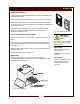
INSTALLATION UNPACKING & INSPECTION Carefully read all instructions in this manual before starting any installation. Carefully remove the hood from the carton. IMPORTANT: Appliance weighs 92 lbs (42.7 kg). Use appropriate care when removing from carton and installing on conveyor warmer. Remove all protective plastic film, packing materials and accessories from the hood before connecting electrical power or otherwise performing any installation procedure.
INSTALLATION (continued) WARNING! Electric Shock hazard All servicing requiring access to non-insulated electrical components must be performed by a factory authorized technician. DO NOT open any access panel which requires the use of tools. Failure to follow this warning can result in severe electrical shock. ELECTRICAL INSTALLATION Refer to the nameplate. Verify the electrical power source. Voltage and phase must match the nameplate specifications.
OPERATION OPERATING CONTROLS Controls include a lighted POWER SWITCH and an amber REPLACE FILTER indicator light. Press POWER SWITCH to ON anytime conveyor warmer is operating. When power is first turned on, the REPLACE FILTER light will glow. As the fan comes up to speed and air flow is established, the REPLACE FILTER light will go out. If the REPLACE FILTER light does not go out, the filters must be replaced. However, the fan will continue to operate when the REPLACE FILTER light is lit.
CLEANING INSTRUCTIONS CAUTION! Personal Injury Hazard Disconnect power from hood and conveyor warmer before cleaning. IMPORTANT: DO NOT spill or pour water into controls, control panel or wiring. DO NOT spill or pour water into exhaust opening. DO NOT submerge hood in water or wash with water or steam spray. Damage to internal components will occur. Damage to internal components from water damage is not covered by warranty.
TROUBLESHOOTING SUGGESTIONS SYMPTOM No operation, no lights REPLACE FILTER light remains lit (never shuts off) If filters are clean and fan is operating If fan is not operating PROBABLE CAUSE CORRECTIVE ACTION Cord unplugged Plug cord into appropriate power receptacle.
SERVICE INSRTUCTIONS IMPORTANT: VACUUM DIAGRAM DO NOT store anything on top of the hood. DO NOT block the exhaust opening. Filter operation is monitored by a vacuum switch and a system of vacuum hoses. The switch energizes the REPLACE FILTER light if airflow through the filters is insufficient for efficient operation. The light is a warning only, and does not control the operation of the hood.
PARTS & SERVICE DESCRIPTION PART NO. HIGH EFFICIENCY FILTER 16 x 20x 4 22862 CHARCOAL (CARBON) FILTER 14 x 20 x 7/8 22403 IMPORTANT: Use only factory authorized service parts and replacement filters. For factory authorized service, or to order factory authorized replacement parts, contact your Wells authorized service agency, or call: Wells Manufacturing Co. 2 Erik Circle P. O. Box 280 Verdi, NV 89439 phone: (775) 689-5700 fax: (888) 492-2783 (Service Parts Dept.