
Specifications


INSTALLATION (continued)
ELECTRICAL INSTALLATION
Refer to the nameplate on the appliance to verify the ELECTRICAL
SERVICE POWER. Voltage and phase must match the nameplate
specifications, and available electrical service amperage must meet or
exceed the specifications listed on page 1. Incoming wiring must
comply with National Electrical Code or International specifications.
UNITED STATES & CANADA
This appliance requires a dedicated 50 amp, 3-phase circuit. Wiring
must be at least 8 ga. copper suitable for a minimum of 90ºC. Wiring
must be installed with a suitable strain relief (provided by electrical
contactor).
INTERNATIONAL
This appliance requires a dedicated 25 amp, 3-phase circuit (L1, L2,
L3, N plus ground). Wiring must be at least 1.5 mm
2
copper suitable for
a minimum of 90ºC. Wiring must be installed with a suitable strain
relief (provided by electrical contactor).
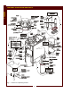
Remove the RIGHT SIDE PANEL. Route supply wiring from the
FEED-THRU on the lower rear panel, then to the terminal block.
Incoming electrical supply is connected to the L1, L2 and L3 (and N for
international) terminals of the TERMINAL BLOCK.
The chassis-mounted GROUND LUG must be connected to earth
ground.
Verify that all connections are tight.
CAUTION:
SHOCK HAZARD
Removal of any exterior panel
will result in exposed electrical
circuits. Electrical connection
must be performed by a
qualified technician only.
Use care whenever working
around exposed electrical
circuits.
IMPORTANT:
Contact a licensed electrician
to install and connect
electrical power to the
fryer.
IMPORTANT:
Damage due to being
connected to the wrong
voltage or phase is NOT
covered by warranty.
CAUTION:
SHOCK HAZARD
Failure to connect the chassis
ground to a suitable earth
ground will result in a potential
shock hazard.
INSTALLATION
7
Fig. 4 Terminal Block Location and Wiring