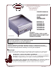
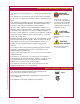
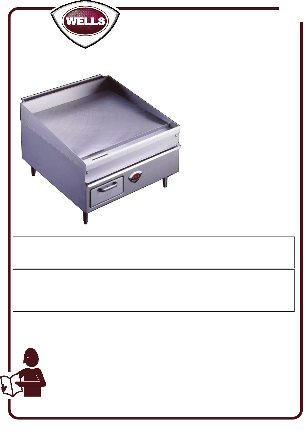
21 WELLS BLOOMFIELD, LLC 10 Sunnen Dr., St. Louis, MO 63143 telephone: 888-356-5362 fax: 314-781-2714 www.wells-mfg.com OWNERS MANUAL COUNTERTOP GAS GRIDDLES MODELS WG2424G WG2436G WG3036G WG3048G Model WG2424G Includes INSTALLATION, USE & CARE EXPLODED VIEW & PARTS LIST WIRING DIAGRAM FOR YOUR SAFETY Do not store gasoline or other flammable liquids in the vicinity of this or any other appliance.
LIMITED WARRANTY STATEMENT based upon the limitations in this warranty. Seller’s obligation under this warranty is limited to the repair of defects without charge by a Wells Bloomfield factory authorized service agency or one of its sub-service agencies. This service will be provided on customer’s premises for non-portable models. Portable models (a device with a cord and plug) must be taken or shipped to the closest authorized service agency, transportation charges prepaid, for service.
TABLE OF CONTENTS WARRANTY SPECIFICATIONS FEATURES & OPERATING CONTROLS PRECAUTIONS & GENERAL INFORMATION AGENCY LISTING INFORMATION INSTALLATION INITIAL ADJUSTMENT OPERATION CLEANING INSTRUCTIONS Standard and GroovedGriddles Chrome-Plated griddles TROUBLESHOOTING SUGGESTIONS WIRING DIAGRAM EXPLODED VIEW & PARTS LIST PARTS & SERVICE CUSTOMER SERVICE DATA xi 1 2 3 4 4 8 10 12 13 14 15 16 27 27 INTRODUCTION Thank You for purchasing this Wells Bloomfield appliance.
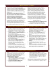
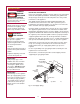
FEATURES & OPERATING CONTROLS SPLASH GUARD GREASE TROUGH GREASE DRAWER FRONT ACCESS PANEL GAS SAFETY VALVE THERMOSTAT ADJUSTABLE LEGS GAS CONTROL KNOB TEMPERATURE CONTROL KNOB IL1833 Fig. 1 Countertop Gas Griddle - Features & Operating Controls FRONT ACCESS PANEL Allows access to gas control valve and themerature control thermostat. Energizes gas valve and allows burners to light based on temp.
PRECAUTIONS AND GENERAL INFORMATION This appliance is intended for use in commercial establishments only. This appliance is intended to prepare food for human consumption. No other use is recommended or authorized by the manufacturer or its agents. This griddle must be installed by a technician qualified and certified or licensed to install gas-fired equipment. A licensed technician must perform the initial startup and adjustment of this appliance.
INSTALLATION DANGER: Health Hazard This appliance must be properly ventilated. Failure to provide proper ventilation of exhaust gasses can result in severe injury and death. WARNING: Fire Hazard Do not store flammable or combustible materials near this appliance. The open flame of this appliance can cause such materials to ignite.
INSTALLATION GAS APPLIANCE CODE COMPLIANCE DANGER: The installation of gas piping from the outlet side of the gas meter or service regulator to the griddle must be performed by a technician qualified and certified or licensed to install gas-fired equipment. Fire and Explosion Hazard A licensed and qualified technician must perform the initial startup and adjustment of this appliance.
INSTALLATION Fire and Explosion Hazard NEVER use an open flame to check for gas leaks. Fire and explosion may result. IMPORTANT: All pipe joints must be checked for leaks before lighting. Leak checks should be performed with a soap and water solution. WARNING: Fire Hazard This griddle is supplied with a gas pressure regulator. Failure to properly install the supplied regulator will result in an extremely hazardous condition. Flow arrow stamped on body of regulator must point toward the griddle.
INSTALLATION GAS PIPE PRESSURE TESTING The main piping system must be capable of supplying the griddle with sufficient volume/flow of fuel to satisfy the maximum operational input requirements. Make sure the supply piping system has been pressure tested before the regulator and griddle are connected. If the system must be re-tested, be sure the regulator is isolated by a manual shut-off valve, in order to prevent damage to the regulator and gas griddle valves.
INITIAL ADJUSTMENT IMPORTANT: PRESSURE ADJUSTMENT MUST BE PERFORMED BY A QUALIFIED TECHNICIAN ONLY. PURGING AIR FROM GAS LINES Air must be purged from the gas lines for the initial startup. Turn the knob on the safety valve to PILOT, press and hold until a flame can be established at the pilot burner. Repeat for each pilot. Caution must be taken to ensure that no raw gas is present in the surrounding area when attempting to place the Griddle into operation.
INITIAL ADJUSTMENT PREPARING THE GRIDDLE SURFACE SEASONING STANDARD GRIDDLES As manufactured, the steel surface of your Wells griddle has microscopic pores. It is important to fill these pores with oil in order to provide a hard, non-stick cooking surface. A. Preheat the griddle surface to 375ºF (191ºC). B. Spread a light film of cooking oil over the entire griddle surface C. Allow the oil film to cook in for approximately 2 minutes, or until it smokes. D.
OPERATION IF YOU SMELL GAS: ¤ DO NOT try to light any appliance. ¤ DO NOT touch any electrical switch ¤ DO NOT use any telephone in your building. In the event a gas odor is detected, shut down the unit at the main gas shutoff valve and contact your local gas supplier from a neighboring location. Follow the instructions received from the gas supplier immediately and exactly. WARNING: Fire Hazard NEVER attempt to force or repair a stuck control valve.
OPERATION USING THE GRIDDLE WARNING: Check the chart below for recommended cooking temperatures. Turn temperature control knob to the desired temperature. Fire and Explosion Hazard For standard griddles: • • • Keep the griddle surface clean and well oiled during use. Scrape cooking waste into the grease trough frequently during use. Occasionally brush or spray a light coat of cooking oil on the griddle surface in order to maintain the non-stick surface.
CLEANING INSTRUCTIONS - STANDARD AND GROOVED GRIDDLES CAUTION: PREPARATION Set temperature control to 220ºF. Allow griddle temperature to drop to 220ºF before proceeding. FREQUENCY Daily TOOLS Griddle Brick or Pumice Stone, Fiber Brush Plastic Scouring Pad, Plastic Scraper Contoured Scraper (grooved griddle) Mild Detergent, Non-Abrasive Cleanser Clean Soft Cloth / Sponge Burn Hazard Griddle will be hot during portions of this cleaning procedure. Always heat-protective gloves and apron.
CLEANING INSTRUCTIONS - CHROME PLATED GRIDDLES PREPARATION Set temperature control to 220ºF. Allow griddle temperature to drop to 220ºF before proceeding. FREQUENCY Daily TOOLS 4” Razor-Style Scraper, Soft Bristle Brush Mild Detergent, Non-Abrasive Cleanser Clean Soft Cloth / Sponge CLEANING Pour a small amount of water on the griddle surface and let it “sizzle”.
TROUBLESHOOTING Pilot will not light Burners won’t light Individual burner won’t light Burner not hot enough Griddle drips grease POSSIBLE PROBLEM SUGGESTED REMEDY Gas supply off Check main / unit gas valves Air in lines Turn gas valve on. Attempt to light pilot every 15 sec. Pilot valve not on or not depressed Refer to page 10 for pilot lighting instructions Pilot light not lit Turn off gas — allow unit to vent for 5 minutes.
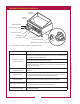
WIRING DIAGRAM THERMOPILE GAS VALVE THERMOSTAT TH/TP TP TH IL2192 M121 p/n 2M- 45324 Owners Manual Countertop Gas Griddles NOTE: Shown is the wiring diagram for a single burner section. Each burner section is wired identically.
EXPLODED VIEW & PARTS LIST WG2424G CABINET COMPONENTS DD-68527A 2H-39039 2 places G7-39331 G7-45951 2 places 2C-35485 G7-45274 G7-45272 2C-35485 G7-45278 2C-33453 2 places 2C-33935 G7-45397 G7-Z12047 2A-Z0314 2R-38668 4 places G7-45271 2M-300534 Model: WG2424G Countertop Gas Griddle: Cabinet Components PL121 IL1836 Rev.
EXPLODED VIEW & PARTS LIST WG2424G FUEL SYSTEM COMPONENTS ADJUSTABLE REGULATOR 2J-39007(NAT) 2J-39284 (LP) REGULATOR CONVERTIBLE FOR LP OR NAT 2J-306629 1 2A-45318 2A-45314 2C-40680 2F-45303 2 places 2 1 1 2T-48817 2 places 2P-39245 2A-45313 2 places 2C-31718 2 2A-45352 (LP) orifice only 2 places 2 M121 p/n 2M- 45324 Owners Manual Countertop Gas Griddles 2A-45315 WS-65307 2 places 2C-33935 2A-45408 (NAT) 2A-39335 (LP) 2R-45321 2 places 2J-45308 pilot plus NAT orifice 2 places 2K-45357 2
EXPLODED VIEW & PARTS LIST WG2436G CABINET COMPONENTS 68528 ASSEMBLY 59039 3 places 65951 59331 3 places 2C-35485 2C-35485 G7-45292 G7-45278 2C-33453 2 places 2C-33935 G7-Z12047 2R-38668 2A-Z0314 4 places 2M-300534 65297 IL1831, Rev A 20 M121 p/n 2M- 45324 Owners Manual Countertop Gas Griddles 59173
EXPLODED VIEW & PARTS LIST WG2436G FUEL SYSTEM COMPONENTS 2J-39007 (NAT) 2J-39284 (LP) 1 2 2A-45318 2A-45314 2F-45303 3 places 3 1 1 2C-40680 WS-65361 2 2P-39245 3 places 2A-45313 3 places 2 2A-45315 2A-45317 2R-45321 3 2T-42195 2K-45357 3 places 2C-31053 2A-45319 3 places Model: WG2436G Countertop Gas Griddle: Fuel System Components PL121 IL1832 Rev.
EXPLODED VIEW & PARTS LIST WG3036G CABINET COMPONENTS 2H-39039 3 places G7-39331 G7-45952 3 places 2C-35485 2C-35485 G7-45292 G7-45278 2C-33453 WS-59173 2C-33935 G7-Z12047 2R-38668 G7-45297 2M-300534 Model: WG3036G IL1838 Rev.
EXPLODED VIEW & PARTS LIST WG3036G FUEL SYSTEM COMPONENTS ADJUSTABLE REGULATOR 2J-39007 (NAT) 2J-39284 (LP) REGULATOR CONVERTIBLE FOR LP OR NAT 2J-306629 1 2 2A-45318 1 2F-45302 1 3 places 2C-40680 3 2A-45314 WS-65361 2 2P-39245 3 places 2A-45317 2A-45313 2C-31718 3 places 2A-45316 3 2A-45408 (NAT) 2A-39335 (LP) 3 places 2R-45321 3 places 3 M121 p/n 2M- 45324 Owners Manual Countertop Gas Griddles 2 2A-45315 WS-65307 2J-45308 3 places pilot plus NAT orifice 3 places 2A-45352 (LP)
EXPLODED VIEW & PARTS LIST WG3048G CABINET COMPONENTS 2H-39039 4 places G7-45952 G7-39331 2C-35485 4 places 2C-35485 G7-45375 G7-45278 2C-33453 WS-59173 G7-Z12047 2R-38668 2C-33935 G7-45373 2M-300534 Model: WG3048G Countertop Gas Griddle: Cabinet Components PL121 IL1840 Rev.
EXPLODED VIEW & PARTS LIST WG3048G FUEL SYSTEM COMPONENTS ADJUSTABLE REGULATOR 2J-39007 (NAT) 2J-39007 (NAT) REGULATOR CONVERTIBLE FOR LP OR NAT 2J-306629 1 2 2A-45318 2A-45314 1 1 3 2F-45302 2 4 places 2 4 2A-45315 DD-60680 3 2A-45317 WS-65361 2A-45316 4 places 3 2A-45319 2C-31718 4 places 4 2A-45352 (LP) 2A-45457 orifice only 4 places 4 M121 p/n 2M- 45324 Owners Manual Countertop Gas Griddles 2P-39245 2A-45313 2R-45321 4 places 2J-45308 WS-65307 pilot plus NAT orifice 4 places
M121 p/n 2M- 45324 Owners Manual Countertop Gas Griddles NOTES 26
PARTS & SERVICE DESCRIPTION SERVICE PART NO. legs, 4”, METAL, set of 4 2a-z0314 SCRAPER, GROOVED GRIDDLE 5G-20651 IMPORTANT: Use only factory authorized service parts and replacement filters. For factory authorized service, or to order factory authorized replacement parts, contact your Wells authorized service agency, or call: Wells Bloomfield, LLC 10 Sunnen Dr., P.O.Box 430129 St. Louis MO 63143 USA Service Dept.
WELLS BLOOMFIELD, LLC 10 Sunnen Dr., St. Louis, MO 63143 telephone: 888-356-5362 fax: 314-781-2714 www.wells-mfg.