705 OWNERS MANUAL WATER-MAX WM-TR Includes INSTALLATION USE & CARE SERVICE IMPORTANT: DO NOT DISCARD THIS MANUAL This manual is considered to be part of the appliance and is to be given to the OWNER or MANAGER of the restaurant, or to the person responsible for TRAINING OPERATORS of this appliance. Additional manuals are available from your WELLS DEALER. THIS MANUAL MUST BE READ AND UNDERSTOOD BY ALL PERSONS USING OR INSTALLING THIS APPLIANCE.
LIMITED WARRANTY STATEMENT GENERAL This Water-Max™ hot water dispenser manufactured by WELLS MFG. CO. is warranted against defects in materials and workmanship for a period of two years from the date of original installation and is for the benefit of the original purchaser only.
GENERAL WARRANTY SPECIFICATIONS FEATURES & OPERATING CONTROLS PRECAUTIONS & GENERAL INFORMATION AGENCY LISTING INFORMATION xi 1 2 4 4 INSTALLATION SET-UP PLUMBING ELECTRICAL INSTALLATION CHECKOUT FORM 5 6 7 9 USE AND CARE USING WATER-MAX™ CLEANING INSTRUCTIONS & DELIMING OVERNIGHT CLEANING 11 12 16 SERVICE & REPAIR TROUBLESHOOTING SUGGESTIONS SAFETY FEATURES & ERROR CODES TEMPERATURE CALIBRATION WIRING DIAGRAM - DISPENSER EXPLODED VIEWS & PARTS LIST - DISPENSER WIRING DIAGRAM - TANK EXPLODED VIEWS & P
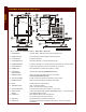
FEATURES & OPERATING CONTROLS GENERAL Fig. 1 Features & Operating Controls - Water Max™ Dispenser 1. STRAIN RELIEF (Left Side, Bottom) Field supply wiring enters the appliance here. 12. DELIMING FITTING Tank mounted quick disconnect fitting for deliming procedure. 22. POWER SWITCH Energizes the appliance. 17. POWER INDICATOR Glows when Water-Max™ is ON and operating normally. 23. DISPENSER NOZZLE Hot water is dispensed here. Inserting water tank lowers nozzle into “dispense” position. 25.
GENERAL FEATURES & OPERATING CONTROLS (continued) Fig. 2 Features & Operating Controls - Water Max™ 5 Gallon Tank 500A. LID HOLDING CLIPS Ears on LID seat in these clips to secure lid to tank. 501. TANK LID Hot water is dispensed into the tank here. Turns clockwise to latch into HOLDING CLIPS. 504. FAUCET PROTECTOR Provides some protection for FAUCET from damage. IMPORTANT: NOT A HANDLE 507. FAUCET ASSEMBLY Controls delivery of hot water to container for food prep, etc. 508.
PRECAUTIONS AND GENERAL INFORMATION GENERAL WARNING: Electric Shock hazard All servicing requiring access to non-insulated electrical components must be performed by a factory authorized technician. DO NOT open any access panel which requires the use of tools. Failure to follow this warning can result in severe electrical shock. CAUTION: Risk of Damage DO NOT connect or energize this appliance until all installation instructions are read and followed.
INSTALLATION Carefully remove the appliance from the carton. Remove all protective plastic film, packing materials and accessories from the appliance before connecting electrical power or otherwise performing any installation procedure. Carefully read all instructions in this manual and the Installation Instruction Sheet packed with the appliance before starting any installation. Read all instructions in this manual carefully before starting installation of this dispenser.
INSTALLATION (continued) CAUTION: Risk of Damage DO NOT connect or energize this appliance until all Installation Instructions are read and followed. Damage to the dispenser will occur if these instructions are not followed. INSTALLATION IMPORTANT: Water supply MUST be a minimum of 1/4” line, and MUST be capable of supplying 25 p.s.i. AT ALL TIMES during the operation of the dispenser. IMPORTANT: Water line material must be rated for at least 180ºF.
INSTALLATION (continued) ELECTRICAL INSTALLATION CAUTION: Conduit, wiring and connections must comply with the specifications in this manual, and with local ordinances. A 208V or 240V single phase, 50 amp circuit required. Field supply wiring must pass thru, and be secured by, the strain relief on the bottom left side of the dispenser. Field wiring supply power must connect to the rear-most side of the terminal block, terminals L1 and L2 as shown in Fig. 4.
INSTALLATION (continued) CAUTION: Hot Surface Exposed surfaces can be hot to the touch and may cause burns. CAUTION: Burn Hazard INSTALLATION WEAR PROTECTIVE GLOVES AND GOGGLES This procedure requires operating Water-Max™ without the tank lid. Some splashing may occur. Splashed water will be very hot. INSTALLATION START-UP AND CHECKOUT Countertop must be at least 17-1/2” deep to safely support the dispenser. Before turning on power or water to Water-Max™, visually verify: a.
INSTALLATION (continued) TYPE OR PRINT CLEARLY Please use a ballpoint pen and press hard. Check boxes and fill in spaces where applicable. To be completed by an Authorized WELLS MFG. Service representative Authorized Service Co.
INSTALLATION (continued) CAUTION: Hot Surface Exposed surfaces can be hot to the touch and may cause burns. START-UP TROUBLESHOOTING Power indicator not lit. a. Verify electrical power is properly hooked-up to Water-Max™ and circuit breaker is turned ON. b. Verify power switch is turned ON. c. Verify that water tank is properly in place and mated with the receptacle. d. Verify water supply is properly installed, is turned on, and is providing at least 25 p.s.i. INSTALLATION Error indicator flashing.
OPERATION WARNING: USING WATER-MAX™ BURN HAZARD Water-Max™ is used to dispense hot water for food preparation. Set-Up and Usage Install the water tank on the Water-Max™ shelf. Make sure that the tank is properly positioned, that the connector is seated and that the dispensing nozzle lowered into position in the water tank lid. Press the power switch to ON and allow the water tank to fill with hot water. Status indicator will glow when the tank is filling.
CLEANING & DELIMING INSTRUCTIONS CAUTION: BURN HAZARD Water in Water-MaxTM is EXTREMELY HOT! Use care when draining tank. CLEANING - DAILY 1. Wipe down unit • Spray a clean, sanitizer-soaked towel with TITAN Solution. • Wipe exterior surfaces. CAUTION: HOT SURFACES Exposed surfaces can be hot to the touch and may cause burns. CAUTION: SHOCK HAZARD DO NOT submerge tank in water USE AND CARE IMPORTANT: DO NOT use bleach, abrasive cleansers or cleansers containing chlorides.
CLEANING & DELIMING INSTRUCTIONS (continued) Deliming Water-MaxTM Continued CAUTION: TM 2. Mix LIMESHIELD • Measure 1/2 cup (4 ounces) of hot tap water. Pour this into the 1 gallon pitcher. • Measure 1/3 cup (2.5 ounces) of LIMESHIELD powder is completely dissolved. • When foaming stops, swirl solution to insure the LIMESHIELD power is completely dissolved. BURN HAZARD Water in Water-MaxTM is EXTREMELY HOT! 3. Insert bottle in Water-MaxTM quick-disconnect fitting.
CLEANING & DELIMING INSTRUCTIONS (continued) Deliming Water-MaxTM Continued CAUTION: BURN HAZARD Water in Water-Max EXTREMELY HOT! TM is 6. Fill bottle with tap water and wait 10 minutes. • Rinse solution bottle with warm tap water. • Fill solution bottle 2/3 full with warm tap water and reattached quick-disconnect cap. • Wait 10 minutes. Insert solution bottle in quick-disconnect fitting. Push down on bottle until latch “clicks”.
CLEANING & DELIMING INSTRUCTIONS ( continued) Deliming Water-MaxTM Continued CAUTION: 9. Remove tank and lid. • Remove tank from Water-MaxTM. • Remove tank lid from tank. Wash, rinse, and sanitize tank lid in the 3-compartment sink. Allow to air dry. Store tank lid for later use. SHOCK HAZARD DO NOT submerge tank in water. 10. Clean tank. • Using a standard green scrub pad, clean all scale and lime from the tank and water level probe.
CLEANING INSTRUCTIONS - OVERNIGHT TANK CLEANING CAUTION: SHOCK HAZARD DO NOT submerge tank in water. OVERNIGHT TANK CLEANING Perform overnight cleaning if Deliming Procedure does not remove scale and calcium deposits from water tank. 1. Drain and remove tank. • Press power switch to the OFF position. • Drain and remove tank from Water-MaxTM. • Remove tank lid from tank. Wash, rinse, and sanitize tank lid in the 3-compartment sink. Allow to air dry. Store tank lid for later use. 2.
CLEANING INSTRUCTIONS - FAUCET & TANK SCREEN CLEANING - MONTHLY CAUTION: Clean Faucet 1. Drain and remove tank. • Press power switch to the OFF position. • Drain all water from tank into pitcher. As each pitcher is full, turn faucet off and dump pitcher of water into sink. It will take approximately 6 pitchers to completely empty tank. • Remove tank from hot water dispenser. 2. Disassemble • Disassemble faucet by unscrewing bonnet. Pull straight up on handle to remove the bonnet assembly. 3.
TROUBLESHOOTING SUGGESTIONS Problem Possible Cause TM • Check circuit Breaker Power switch OFF • Press power switch to ON • Insufficient water supply • Check water supply turned ON and supplying at least 25 p.s.i. • Blown Fuse • Contact maintenance Tank indicator not lit • Tank not properly seated in socket • Check tank for proper installation Status indicator flashing • ERROR detected—water pressure insufficient • Check water supply turned ON and supplying at least 25 p.s.i.
SAFETY FEATURES & ERROR CODES SAFETY FEATURES CAUTION: Water-Max™ will not flow water from the dispense nozzle unless the water tank is in place. (Error lamp and audible alarm on continuously.) SHOCK HAZARD Water-Max™ will not dispense into a full water tank. The water tank heater will not heat unless the connector on WaterMax™ is fully mated with the tank receptacle. The heater on the water tank is protected by an over-temp safety switch which will disable the heater if the tank is allowed to run dry.
CALIBRATING TEMPERATURE CAUTION: SHOCK HAZARD Removal of the top, front or side panels results in exposed electrical circuits. Setting the temperature must be performed by a qualified technician only. Use care whenever working around exposed electrical circuits. Remove TOP PANEL. Insert the thermocouple of a digital thermometer at least 4” into DISPENSER NOZZLE. Install WATER TANK under DISPENSER NOZZLE. Press POWER SWITCH to ON.
CALIBRATE DELIME INDICATOR TEST / ADJUST DELIME SENSOR: CAUTION: BURN HAZARD Reconnect Water-Max™ to electric power. Remove the plastic cover from the tank, then reinstall the tank on the tank shelf. Tank must be empty to begin test. Insert the thermocouple of a digital thermometer approximately 6" into the spout. Be sure thermocouple is into the silicone tube section. Press the power switch ON. Observe the action of the DELIME LED. Dispensed water is hot. Use care to avoid splashing or spills.
EXPLODED VIEW & PARTS LIST - DISPENSER SERVICE 22
EXPLODED VIEW & PARTS LIST - DISPENSER (continued) SERVICE WATER-MAX™ DISPENSER 23
WIRING DIAGRAM - DISPENSER SERVICE 24
SERVICE EXPLODED VIEW, PARTS LIST & WIRING DIAGRAM - 5 GALLON TANK 25
SERVICING INSTRUCTIONS THE FOLLOWING COMPONENTS MAY BE SERVICED IN-STORE CABINET COMPONENTS SERVICE 26
SERVICING INSTRUCTIONS (continued) CABINET COMPONENTS WARNING Electric Shock Hazard A. TANK SHELF 1. Removal a. Remove two screws (g). b. Lift the front of the tank shelf until the rear lip clears the front assembly. c. Lift the tank shelf off. 2. Installation a. Hold tank shelf vertically. Slide rear lip under front assembly. b. Rotate tank shelf to the horizontal position. The left and right lips go on the outside of the wrap. The flange with the weldnuts (g) goes behind the front web of the wrap. c.
SERVICING INSTRUCTIONS (continued) TOOLS REQUIRED: #2 Phillips Screwdriver Container to hold fasteners D. TOP COVER AND WRAP ASSEMBLY Note: For the purpose of servicing Water-Max™, the top cover and wrap may be removed as a unit. 1. Removal a. Remove the tank shelf, support cover and front assembly. (see A., B. and C., page 25). b. Remove four screws (d) from the area beneath the shelf. c. Remove screw (f) from power board support. d. Loosen three chassis screws (e). e.
SERVICING INSTRUCTIONS (continued) HOSE CLAMPS TOOLS REQUIRED: 1. Hose clamps used on Water-Max™ are reusable. DO NOT cut hose clamps. Needle Nose Pliers 2. Open clamp by twisting an ear until the fingers slide past one an other and release. SERVICE 3. Tighten clamp by squeezing ears together.
SERVICING INSTRUCTIONS (continued) WARNING Electric Shock Hazard Disconnect Water-Max™ from electrical power before removing any panel or cover. CONTACTOR Repair time not to exceed 0.5 hour A. Preparation 1. Disconnect Water-Max™ from electrical power. 2. Shut off water supply to Water-Max™. B. Removal TOOLS REQUIRED: #2 Phillips Screwdriver Container to hold fasteners Flat Blade Screwdriver Needle Nose Pliers 11/32” Nut Driver 1. Remove top cover and wrap (see page 28) 2.
SERVICING INSTRUCTIONS (continued) SCR ASSEMBLY Repair time not to exceed 1.0 hour WARNING Electric Shock Hazard A. Preparation Disconnect Water-Max™ from electrical power before removing any panel or cover. 1. Disconnect Water-Max™ from electrical power. 2. Shut off water supply to Water-Max™. B. Removal 1. Remove top cover and wrap (see page 28) 2. Disconnect the contactor shelf: a. Remove two nuts at the corners of the shelf. b. Lift the shelf only enough to gain access to the SCR heatsink screws. 3.
SERVICING INSTRUCTIONS (continued) WARNING Electric Shock Hazard Disconnect Water-Max™ from electrical power before removing any panel or cover. COOLING FAN Repair time not to exceed 1.0 hour A. Preparation 1. Disconnect Water-Max™ from electrical power. 2. Shut off water supply to Water-Max™. B. Removal TOOLS REQUIRED: #2 Phillips Screwdriver Container to hold fasteners Needle Nose Pliers 7/16” & 9/16” Open End Wrenches 1. Remove top cover and wrap (see page 28) 2. Disconnect cleanout assembly: a.
SERVICING INSTRUCTIONS (continued) POWER SWITCH Repair time not to exceed 0.5 hour WARNING Electric Shock Hazard A. Preparation Disconnect Water-Max™ from electrical power before removing any panel or cover. 1. Disconnect Water-Max™ from electrical power. 2. Shut off water supply to Water-Max™. B. Removal 1. 2. 3. 4. Remove front assembly and tank shelf (see page 27). Remove paper shield. Note position of wires on switch. Disconnect wires. Compress mounting fingers on switch.
SERVICING INSTRUCTIONS (continued) WARNING Electric Shock Hazard INLET WATER VALVE ASSEMBLY Repair time not to exceed 0.5 hour (replace valve), or 1.0 hour (clean strainer screen) Disconnect Water-Max™ from electrical power before removing any panel or cover. A. Preparation TOOLS REQUIRED: B. Removal #2 Phillips Screwdriver Container to hold fasteners Needle Nose Pliers 2 ea. 5/8” Open End Wrenches Brush (Toothbrush or similar) 1. Disconnect Water-Max™ from electrical power. 2.
SERVICING INSTRUCTIONS (continued) INLET WATER PRESSURE SWITCH Repair time not to exceed 0.5 hour WARNING Electric Shock Hazard A. Preparation Disconnect Water-Max™ from electrical power before removing any panel or cover. 1. Disconnect Water-Max™ from electrical power. 2. Shut off water supply to Water-Max™. B. Removal 1. 2. 3. 4. Remove front assembly and tank shelf (see page 28). Remove paper shield. Disconnect wires. Unscrew old pressure switch from brass tee fitting. Discard old switch.
SERVICING INSTRUCTIONS (continued) WARNING Electric Shock Hazard Disconnect Water-Max™ from electrical power before removing any panel or cover. CAUTION: SHOCK HAZARD Removal of the top, front or side panels results in Exposed electrical circuits. Setting the temperature must be performed by a qualified technician only. Use care whenever working around exposed electrical circuits. POWER BOARD Repair time not to exceed 1.0 hour (including calibration) A. Preparation 1.
SERVICING INSTRUCTIONS (continued) D. Return Unit to Service Disconnect Water-Max™ from electrical power before removing any panel or cover. CAUTION: SHOCK HAZARD Removal of the top, front or side panels results in Exposed electrical circuits. Setting the temperature must be performed by a qualified technician only. Use care whenever working around exposed electrical circuits. NOTE: The practical maximum temperature is the local boiling temperature (based on the altitude of the installation) minus 10ºF.
SERVICING INSTRUCTIONS (continued) CAUTION: Burn Hazard Carefully empty water from tank and remove tank from WaterMax™ and before performing any servicing. TOOLS REQUIRED: 18” Adjustable Wrench Container to hold fasteners Teflon Thread Tape Food-Grade Silicone Sealant FAUCET AND SHANK ASSEMBLY Repair time not to exceed 0.5 hour A. Removal and Disassembly 1. Carefully drain all water from the tank. Remove the tank from Water-Max™. Remove the tank lid from the tank and store in a safe place. 2.
SERVICING INSTRUCTIONS (continued) DISPENSER TANK CAUTION: Burn Hazard A. Tank Disassembly (refer to page 25) 1. Carefully drain all water from the tank. Remove the tank from Water-Max™. Remove the tank lid from the tank and store in a safe place. 2. Remove temperature gauge and holding nut from tank. 3. Disassemble faucet shank assembly (see page 38). 4. Remove four screws from side lips of reservoir assembly. 5. Lift tank reservoir assembly out of wrap. 6. Disconnect wiring as required. B. Reassembly 1.
SERVICING INSTRUCTIONS (continued) CAUTION: Burn Hazard Carefully empty water from tank and remove tank from WaterMax™ and before performing any servicing. TOOLS REQUIRED: #2 Phillips Screwdriver 7/16” Open-End Wrench Container to hold fasteners Food-Grade Silicone Sealant Note: Be careful to avoid scraping, trapping or pinching wires as the reservoir is lowered into the wrap. LOW WATER LEVEL PROBE Repair time not to exceed 0.5 hour A. Removal and Disassembly 1. Carefully drain all water from the tank.
PARTS & SERVICE ACCESSORIES & OPTIONAL COMPONENTS DESCRIPTION PART NO. WALL MOUNT KIT, SIDE MOUNT MOUNTS WATER-MAX™ WITH FAUCET TO THE LEFT SIDE 22687 WALL MOUNT KIT, BACK MOUNT MOUNTS WATER-MAX™ WITH FAUCET TO THE FRONT 22726 TANK, 5 GALLON, MODEL DT-5 22658 PITCHER, PLASTIC, 4 QT.