705 WELLS MANUFACTURING COMPANY 2 ERIK CIRCLE, P. O. Box 280 Verdi, NV 89439 Customer Service (775) 345-0444 Ext.502 fax: (775) 345-0569 www.wellsbloomfield.com SERVICE MANUAL WATER-MAX WM-TR Includes SERVICE INSTRUCTIONS WIRING DIAGRAMS EXPLODED VIEWS PARTS LIST IMPORTANT: DO NOT DISCARD THIS MANUAL This manual is considered to be part of the appliance and is to be given to the OWNER or MANAGER of the restaurant, or to the person responsible for TRAINING OPERATORS of this appliance.
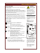
PRECAUTIONS AND GENERAL INFORMATION WARNING: Electric Shock hazard All servicing requiring access to non-insulated electrical components must be performed by a factory authorized technician. DO NOT open any access panel which requires the use of tools. Failure to follow this warning can result in severe electrical shock. CAUTION: Risk of Damage DO NOT connect or energize this appliance until all installation instructions are read and followed.
TABLE OF CONTENTS PRECAUTIONS & GENERAL INFORMATION SPECIFICATIONS TROUBLESHOOTING SUGGESTIONS SAFETY FEATURES & ERROR CODES TEMPERATURE CALIBRATION CLEANING INSTRUCTIONS DELIMING INSTRUCTIONS SERVICING INSTRUCTIONS WIRING DIAGRAM - DISPENSER EXPLODED VIEWS & PARTS LIST - DISPENSER WIRING DIAGRAM - TANK EXPLODED VIEWS & PARTS LIST - DISPENSER xi 1 2 3 4 5 8 9 23 24 25 26 SPECIFICATIONS Electrical: 208 Volts, Single Phase 35 Amps 240 Volts, Single Phase 35 Amps NOTE: Requires a dedicated 50 Amp circuit
TROUBLESHOOTING SUGGESTIONS SYMPTOM POSSIBLE CAUSE SUGGESTED REMEDY POWER INDICATOR not lit Water-Max™ not connected to power Check POWER PLUG Check circuit breaker POWER switch OFF Press POWER switch to ON Insufficient water supply Check water supply turned ON And supplying at least 25 p.s.i.
SAFETY FEATURES & ERROR CODES SAFETY FEATURES CAUTION: Water-Max™ will not flow water from the dispense nozzle unless the water tank is in place. SHOCK HAZARD Water-Max™ will not dispense into a full water tank. The water tank heater will not heat unless the connector on WaterMax™ is fully mated with the tank receptacle. The heater on the water tank is protected by an over-temp safety switch which will disable the heater if the tank is allowed to run dry.
CALIBRATING TEMPERATURE CAUTION: SHOCK HAZARD Removal of the top, front or side panels results in exposed electrical circuits. Setting the temperature must be performed by a qualified technician only. Use care whenever working around exposed electrical circuits. Remove TOP PANEL. Insert the thermocouple of a digital thermometer at least 4” into DISPENSER NOZZLE. Install WATER TANK under DISPENSER NOZZLE. Press POWER SWITCH to ON.
CLEANING INSTRUCTIONS DAILY CLEANING CAUTION: PRECAUTIONS: Press POWER SWITCH to OFF (0). Drain all water from TANK. Remove tank from Water-Max™. FREQUENCY: Minimum - Daily, or as required TOOLS: Soft Cloth, Soft Bristle Brush BURN HAZARD Water in tank is extremely hot. Use care when draining tank. CAUTION: HOT SURFACES Exposed surfaces can be hot to the touch and may cause burns.
DELIMING INSTRUCTIONS CAUTION Burn Hazard DELIMING INSTRUCTIONS PRECAUTIONS: Water in tank is EXTREMELY HOT (over 200ºF) Turn Water-Max™ OFF Water in Water-Max™ is EXTREMELY HOT Drain water from tank before moving. FREQUENCY: Weekly, or as required when Water-Max™ will not maintain water at preset temperature. TOOLS: LIMESHIELD™ Scale and Food Soil Inhibitor Funnel, Solution Bottle Scrub Pad (Standard Green) 1 Gallon or Larger Plastic Container (Pitcher) 1.
DELIMING INSTRUCTIONS (continued) SQUEEZE 4. Squeeze solution bottle and force deliming solution into WaterMax™ 5. Press latch on tank quick-disconnect fitting until it “clicks” to release the solution bottle. Lift solution bottle straight up. Unscrew quick-disconnect cap allowing solution bottle to return to shape. Rinse solution bottle with warm tap water. Fill solution bottle 2/3 full of warm tap water and reattach quick-disconnect cap.
DELIMING INSTRUCTIONS (continued) 7. Remove tank from Water-Max™ Remove TANK COVER from tank. Rinse cover and dry. Store tank cover for later use. Note: See Cleaning Instructions page 15. REMOVE TANK REMOVE LID 8. WATER LEVEL PROBE is located in the tank, in the back right corner near the top. SCRUB TANK Using a STANDARD GREEN SCRUB PAD, clean all scale and lime from the water level probe.
SERVICING INSTRUCTIONS CABINET COMPONENTS 9
SERVICING INSTRUCTIONS (continued) WARNING Electric Shock Hazard Disconnect Water-Max™ from electrical power before removing any panel or cover. IMPORTANT Shut off water supply before performing any service to Water-Max™ CABINET COMPONENTS A. TANK SHELF 1. Removal a. Remove two screws (g). b. Lift the front of the tank shelf until the rear lip clears the front assembly. c. Lift the tank shelf off. 2. Installation a. Hold tank shelf vertically. Slide rear lip under front assembly. b.
SERVICING INSTRUCTIONS (continued) D. TOP COVER AND WRAP ASSEMBLY TOOLS REQUIRED: Note: For the purpose of servicing Water-Max™, the top cover and wrap may be removed as a unit. #2 Phillips Screwdriver Container to hold fasteners 1. Removal a. Remove the tank shelf, control cover and front assembly. (see A., B. and C., page 10). b. Remove four screws (d) from the area beneath the shelf. c. Remove screw (f) from power board support. d. Loosen three chassis screws (e). e.
SERVICING INSTRUCTIONS (continued) WARNING Electric Shock Hazard Disconnect Water-Max™ from electrical power before removing any panel or cover. CONTACTOR Repair time not to exceed 0.5 hour A. Preparation 1. Disconnect Water-Max™ from electrical power. 2. Shut off water supply to Water-Max™. B. Removal TOOLS REQUIRED: #2 Phillips Screwdriver Container to hold fasteners Flat Blade Screwdriver Needle Nose Pliers 11/32” Nut Driver 1. Remove top cover and wrap (see page 11) 2.
SERVICING INSTRUCTIONS (continued) SCR ASSEMBLY Repair time not to exceed 1.0 hour WARNING Electric Shock Hazard A. Preparation Disconnect Water-Max™ from electrical power before removing any panel or cover. 1. Disconnect Water-Max™ from electrical power. 2. Shut off water supply to Water-Max™. B. Removal 1. Remove top cover and wrap (see page 11) 2. Disconnect cleanout assembly: a. Disconnect hose clamp on supply hose. Remove supply hose. b. Disconnect flare fitting from inductive heater inlet tube.
SERVICING INSTRUCTIONS (continued) WARNING Electric Shock Hazard Disconnect Water-Max™ from electrical power before removing any panel or cover. COOLING FAN Repair time not to exceed 1.0 hour A. Preparation 1. Disconnect Water-Max™ from electrical power. 2. Shut off water supply to Water-Max™. B. Removal TOOLS REQUIRED: #2 Phillips Screwdriver Container to hold fasteners Needle Nose Pliers 7/16” & 9/16” Open End Wrenches 1. Remove top cover and wrap (see page 11) 2. Disconnect cleanout assembly: a.
SERVICING INSTRUCTIONS (continued) POWER SWITCH Repair time not to exceed 0.5 hour WARNING Electric Shock Hazard A. Preparation Disconnect Water-Max™ from electrical power before removing any panel or cover. 1. Disconnect Water-Max™ from electrical power. 2. Shut off water supply to Water-Max™. B. Removal 1. 2. 3. 4. Remove front assembly and tank shelf (see page 10). Remove paper shield. Note position of wires on switch. Disconnect wires. Compress mounting fingers on switch.
SERVICING INSTRUCTIONS (continued) WARNING Electric Shock Hazard INLET WATER VALVE ASSEMBLY Repair time not to exceed 0.5 hour (replace valve), or 1.0 hour (clean strainer screen) Disconnect Water-Max™ from electrical power before removing any panel or cover. A. Preparation TOOLS REQUIRED: B. Removal #2 Phillips Screwdriver Container to hold fasteners Needle Nose Pliers 2 ea. 5/8” Open End Wrenches Brush (Toothbrush or similar) 1. Disconnect Water-Max™ from electrical power. 2.
SERVICING INSTRUCTIONS (continued) INLET WATER PRESSURE SWITCH Repair time not to exceed 0.5 hour WARNING Electric Shock Hazard A. Preparation Disconnect Water-Max™ from electrical power before removing any panel or cover. 1. Disconnect Water-Max™ from electrical power. 2. Shut off water supply to Water-Max™. B. Removal 1. 2. 3. 4. Remove front assembly and tank shelf (see page 10). Remove paper shield. Disconnect wires. Unscrew old pressure switch from brass tee fitting. Discard old switch. C.
SERVICING INSTRUCTIONS (continued) WARNING Electric Shock Hazard Disconnect Water-Max™ from electrical power before removing any panel or cover. CAUTION: SHOCK HAZARD Removal of the top, front or side panels results in Exposed electrical circuits. Setting the temperature must be performed by a qualified technician only. Use care whenever working around exposed electrical circuits. POWER BOARD Repair time not to exceed 1.0 hour (including calibration) A. Preparation 1.
SERVICING INSTRUCTIONS (continued) D. Return Unit to Service 1. Turn water supply on and check for leaks. 2. Connect Water-Max™ to electrical power. 3. Calibrate power board. See drawing below. a. Insert the thermocouple of a digital thermometer at least 4” into dispenser nozzle. b. Install water tank under dispense nozzle. Press power switch ON. c. Run and discard at least one full tank of hot water to allow dispenser temperatures to stabilize. d. Temperature is factory set for 201ºF.
SERVICING INSTRUCTIONS (continued) CAUTION: Burn Hazard Carefully empty water from tank and remove tank from WaterMax™ and before performing any servicing. TOOLS REQUIRED: 18” Adjustable Wrench Container to hold fasteners Teflon Thread Tape Food-Grade Silicone Sealant FAUCET AND SHANK ASSEMBLY Repair time not to exceed 0.5 hour A. Removal and Disassembly 1. Carefully drain all water from the tank. Remove the tank from Water-Max™. Remove the tank lid from the tank and store in a safe place. 2.
SERVICING INSTRUCTIONS (continued) DISPENSER TANK CAUTION: Burn Hazard A. Tank Disassembly (refer to page 27) 1. Carefully drain all water from the tank. Remove the tank from Water-Max™. Remove the tank lid from the tank and store in a safe place. 2. Remove temperature gauge and holding nut from tank. 3. Disassemble faucet shank assembly (see page 20). 4. Remove four screws (517) from side lips of reservoir assembly. 5. Lift tank reservoir assembly out of wrap. 6. Disconnect wiring as required. B.
SERVICING INSTRUCTIONS (continued) CAUTION: Burn Hazard Carefully empty water from tank and remove tank from WaterMax™ and before performing any servicing. TOOLS REQUIRED: #2 Phillips Screwdriver 7/16” Open-End Wrench Container to hold fasteners Food-Grade Silicone Sealant Note: Be careful to avoid scraping, trapping or pinching wires as the reservoir is lowered into the wrap. LOW WATER LEVEL PROBE Repair time not to exceed 0.5 hour A. Removal and Disassembly 1. Carefully drain all water from the tank.
WIRING DIAGRAM - DISPENSER 23
EXPLODED VIEW & PARTS LIST - DISPENSER WATER-MAX™ DISPENSER 24
EXPLODED VIEW & PARTS LIST - DISPENSER (continued) 25
WIRING DIAGRAM - TANK RECEPTACLE WATER LEVEL PROBE ORANGE L2 BLACK GREEN L1 TANK GND HEATING ELEMENT (100W) RED OVER-TEMP SAFETY SWITCH SCHEMATIC FOR 240V 400W 5 GAL TANK EXPLODED VIEW & PARTS LIST - TANK WATER-MAX™ 5 - GALLON WATER TANK 26 HEATING ELEMENT (300W)
EXPLODED VIEW & PARTS LIST - TANK (continued) 501 520 4 pl 517 504 519 518 508 512 2 pl 2 pl 514 510 513 505 4 pl 516 506 2 pl 509 515 4 pl 511 part of item 507. 507 p/n 75013 Rev.
WELLS MANUFACTURING COMPANY DIVISION OF CARRIER REFRIGERATION 2 ERIK CIRCLE, P. O. Box 280 Verdi, NV 89439 Customer Service (775) 345-0444 Ext.502 fax: (775) 345-0569 www.wellsbloomfield.