
Owner's manual


19
REPLACING BLADE ON SAW
Saws with Double Spring Tensioner
Gloves must be worn for this operation.
1. Raise saw head far enough for the blade to clear the
top of the vise jaws.
2. Open both Wheel doors and open blade guards
3. Push blade brush idler arm away from the belt to re-
lease the tension and remove the belt.
4. On both blade guides turn the black knurled knob coun-
ter-clockwise until it stops. This opens the carbides.
5. Turn the Blade Tensioner T handle counter-clockwise
until the blade comes free from the bandwheels and
remove the band.
6. Install the new band around the bandwheels and into
the blade guides. Be sure that the teeth are pointing
away from the fl ange of the wheel. The teeth should
hang over the edge of the wheel. Also be sure that the
teeth are pointing in the direction that the blade will
travel.
7. Check to be sure that the blade is fully up into both
blade guides.
8. Turn the T Handle of the tensioner until the blade be-
comes snug on the wheels. Pull the blade up against
the wheel fl ange.
9. Continue to tighten the T Handle until the Pointer
reaches the block. See picture.
10. Turn knobs on blade guides fully clock-wise. This
closes the carbides.
11. Install blade brush belt and close the guards and wheel
doors.
12. After fi ve minutes of operation stop the saw and open
the wheel doors. Inspect to be sure that the back edge
of the blade is properly tracking up to the fl ange of the
wheel. If the band is not tracking properly damage to
the wheels will result.
SUPPLEMENTAL FEED PRESSURE SYSTEM
This system provides additional sawing downforce to en-
sure a positive chip load when the saw head angle is high
such as when cutting a large diameter solid stock. It is also
helpful when sawing very tough materials. The system con-
sists of an air-over-oil volume chamber and an air pressure
regulator. Oil under pressure is applied to the top of the saw
head lifting cylinder. The pressure is adjusted at the second
regulator mounted on the side of the saw. For basic opera-
tion, the pressure should be set to 5 to 10 PSI. For large
or tough solid stock the pressure can be increased to a
maximum of 20 PSI.
An oil level sight gauge is provided. Check the oil level with
the saw head is all the way down. The maximum level is
at the top ferrule. The minimum is half way down the sight
gauge.
To add oil, remove machine air pressure and remove the
pipe plug at the top of the sight gauge. Open the air line at
the exit port of the regulator. Fill to just below the top of the
sight gauge.
WHEEL PITCH ADJUSTMENT
If the saw blade runs too low, runs off the wheels, or runs
too high and rubs the wheel fl ange, a wheel adjustment
must be made. Loosen the blade before making the follow-
ing adjustments:
IDLER WHEEL
• Blade running too low or off the wheel.
Adjust the idler wheel block. Loosen the 2 cap screws
in the block opposite the take up screw end, one-half
(½) turn. Tighten the opposite 2 cap screws one-half
(½) turn. Repeat if necessary.
• Blade running too high and against the idler wheel
fl ange.
The blade can become distorted, its top edge rolled
over and wheel fl ange will wear excessively. To cor-
rect this, loosen the two cap screws closest to the take
up screw one-half (½) turn. Tighten the opposite cap
screws one-half (½) turn. Repeat if necessary.
DRIVE WHEEL
• Blade running too low or off the drive wheels.
Loosen the two cap screws opposite the outside end of
the wheel plate one-half (½) turn. Tighten the two set
screws on the same end one-half (½) turn. Repeat if
necessary.
• Blade running too high, and against the drive wheel
fl ange.
Loosen the cap screws closest to the outside end of
GENERAL OPERATING INFORMATION
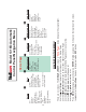
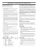
Blade Tension Mechanism
1. 101184 T-Handle
2. 100030-007 Flat Washer, 1/2
3. 100410-001 Thrust Bearing
4. 107321 Take Up Screw
5. 155259 Tensioner Slide Assembly
6. 101198 Spring
7. 155262 Tensioner Support
8. 155263 Tensioner Slide Stop
9. 100013-009 Cap Screw, BH, 10-32 x 1/2
10. 100053-005 Roll Pin, 3/16 x 1
11. 100008-006 Cap Screw, SH, 3/8-16 x 1