
Data Sheet


Specifications on this catalog are for reference only, as they are subject to change without notice.
91
www.acptechnologies.com
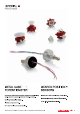
ACP’s switches (COM) follow the same configuration as the potentiometers, as shown in previous sections of this catalogue. The word COM needs to be added to the
description. The cells 5, 6 and 7 (value, taper and tol) are left blank. If the switching angle is different from our standard, then it should be indicated.
Electric
Specifications
Please, note that these are standard features; other specifications are available on request.
COM CA6
Resistive element
Switching angle at ON position
≤5Ω
Operating temperature
Carbon
Power ratio 15V / 12mA
Resistance at ON position
Dielectric Strength
Electric
Function
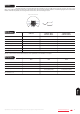
The three terminals of the potentiometer are equivalent to one input (B) and two outputs (A and C), as shown in the
figure. The middle terminal (B) corresponds to the internal wiper, which switches between positions. The switching angle can be customized.
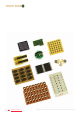
Unless otherwise requested, the housing will be neutral color, with the marking in black.
A
B C
A
(ON)
C
(ON)
switching
angle
switching
angle
B
A
C
Angle
of
rotation
(mechanical)
3
0
°
3
0
°
Insulation resistance
COM CA9 / MCA9
COM CA14 / MCA14
Mechanical
Specifications
Angle of rotation
235º ± 10º
Wiper torque
Max. stop torque
Max. push/pull on rotor
9.8 N
COM CE9 / MCE9
COM CE14 / MCE14
Carbon Cermet
24V / 12mA 24V / 12mA
≤5Ω ≤5Ω
600V 1500V 1500V
100MΩ 100GΩ 100GΩ
20º ± 15º 30º ± 15º 30º ± 15º
-25ºC... +70ºC (+85ºC) -40ºC... +90ºC (+125ºC)
6mm 9mm 14mm
Mechanical life
1.000
< 2 Ncm
4 Ncm
240º ± 5º
40 N / 50 N
1.000
< 2 Ncm
5 Ncm (CA9, CE9)
25 Ncm (MCA9, MCE9)
10 Ncm (CA14, CE14)
15 Ncm (MCA14, MCE14)
40 N / 50 N
265º ± 5º
1.000
< 2.5 Ncm
COM