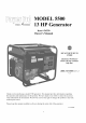
MODEL 5500 13 HP Generator Item # 56550 Owner's Manual DO NOT RETURN STORE TO Questions? Problems? Please call our customer help line: (888) 315-3080 CT M-F 8-5 ThaN< you for purchasing a model 5500 generator. This manual provides information regarding the operation and maintenance of this product. We have made every effort to ensure the accuracy of the information in this manual. Wen Power reserves the right to change this product at any time without Please prior notice.
MODEL 5500 13 HP Generator FEATURES • 5500 Surge Watt Output • 5000 Rated Watt Output • Powerful Enough to Run Essential Appliances During Power Outages • 120 and 240 VoltAC Outputs • DC Output for Automotive Battery Charging • Low OilAutomaticShutoff • Circuit Breaker for Overload Protection • 6.
TABLE OF CONTENTS GENERAL SAFETY PROCEDURES ........................................................................ PACKAGE CONTENTS ....................................................................................... GENERATOR COMPONENTS .............................................................................. PREPARING THE GENERATOR FOR USE ............................................................... Using the Generator tbr the First Time .....................................................
GENERAL Please SAFETY familiarize yourself The safety alert symbol or WARNING) in this manual PROCEDURES with the lbllowing symbols _t, is used with one of the safety to alert you to hazards. Please and words: words pay attention (DANGER, CAUTION, to these hazard notices both and on the generator. DANGER: Indicates not followed. a hazard that will result WARNING: instructions Indicates a strong possibility are not lbllowed.
WARNING: electrocution. • • This generator ALWAYS ground Generator" section). portion Generator should produces the generator powerful betbre of the "PREPARING only be plugged using voltage, which can result it (see the "Grounding THE GENERATOR into electrical devices, in the FOR USE" either directly or with an extension cord. NEVER connect to a building electrical system without a qualified electrician. Such connections must comply with local electrical laws and codes.
In addition hazard to the above safety markings Stop generator - Check notices, on the generator. before for spilled refueling fuel, Do not operate near open flame, IMPORTANT_ BEFORE STARTING:: _, Mak_ s_e _tt is p_ope_ly 9tour_ed, 2. Gh_ck {hat ¢r_N_ 3.
PACKAGE CONTENTS Your generator comes with the items listed below. tbllowing items are included with your generator. If you are missing 315-3080 components M-F 8-5 CT for customer DO NOT Please RETURN check to see that all of the TO STORE, please call (888) service. ITEM LIST .................. AC plug tbr connecting 240 Volt electrical devices G PLUG WRENCH Spark plug wrench HANDLE BAR Flat Head Screwdriver Set 2 of connecting batteries.
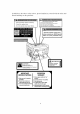
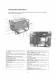
GENERATOR COMPONENTS Please familiarize yourself with the locations and controls of your generator. 7 8 9 10 and functions of the various components t1 1 2 t2 !4 4 17 _8 !5 19 (1) Choke Rod- Adjusts the amount of air let into the engine. (2) Air cleaner- a removable, cleanable, sponge-like element that limits the amount of dirt pulled into the engine. (3) Fuel valve- Allows fuel to enter engine. (4) Fuel Filter Cup- Traps dirt and water fi:om fuel before it enters the engine.
PREPARING Usin_ @ THE the Generator The following for first-time use. to perform FOR USE for the First Time section describes If after reading any of the steps please Failure GENERATOR call (888) these steps you this" section, 315-3080 steps properly If you are using the generator prepare it for operation: must follow you M-F can damage to prepare are unsure 8-5 your generator about how to perform CT for customer your generator service. or shorten its" life.
Step 2- Add Gasoline _1_WARNING: Gasoline and gas fumes are highly • Do not fill tank near an open flame. • Do not overfill. Always check flammable. for fuel spills. To ensure that the generator runs Slnoothly use only FRESH, UNLEADED AN OCTANE RATING OF 87 OR HIGHER. To add gasoline: GAS WITH 1. 2. Make sure the generator is on a level surface. Unscrew gas cap and set aside (NOTE: the gas cap may be tight and hard to unscrew). 3. Slowly add unleaded gasoline to the fuel tank.
Subsequent Use of the Generator If this is not your first time using the generator prepare it tbr operation. IMPORTANT: At this point you should in the first portion of this section entitled If you have not yet read Step 1- Check the Oil The generator is equipped this section, there are still steps you should take to be familiar with the procedures described "Using the Generator for the First Time." go back with an automatic and read shutoffto it now.
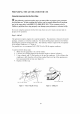
Step 3- Ground A WARNING: Ground the Generator Failure the generator to properly by tightening ground the generator the grounding can result nut against in electrocution. a grounding wire (see figure 3). A generally acceptable grounding wire is a No. 12 AWG (American Wire Gauge) stranded copper wire. This grounding wire should be connected at the other end to a copper or brass grounding Grounding codes can vary by location.
CHOKE OFF ROD OPEN CLOSED Figure 4- Fuel Valve in the "on" Figure 5- (hoke position rod positions Figure 6- Pulling the start cord USING Once devices THE GENERATOR you have allowed the engine to run for several minutes, you may connect electrical to the generator. AC Usage You may connect requirements. The rated continuous electrical The chart wattage basis.
wattageof eachdevice.Thisnumbershouldbelistedsomewhere on thedeviceor in its instructionmanual.If youcannotfind this wattage,you maycalculateit by multiplying the Voltagerequirementby the Amperagedrawn: Watts= Volts x Amperes If thesespecificationsarenot availableyoumayestimatetheWattsrequiredby your deviceby usingthe chartin figure8. Onceyouhavefoundthe ratedwattagerequirementof eachelectricaldevice,addthese numbersto find thetotal ratedwattageyou wishto drawfrom thegenerator.
NOTE: Theabovewattagefiguresareestimates.Try to checkthe wattagelistedonyour electricaldevicebeforeconsultingthis chart Onceyouhavedeterminedwhatelectricaldevicesyouwill bepoweringwith the generator,connectthesedevicesaccordingto the followingprocedure: 1. Plug in each electrical device with the device turned off. NOTE: Be sure to attach appliances to the correct receptacle (outlet). Connect standard 120 Volt, single phase, 60 Hz loads only to the 120 Volt receptacles.
SOME NOTES ABOUT POWER CORDS Long or thin cords can drain the power provided to an electrical device by the generator. When using such cords, allow tbr a slightly higher rated wattage requirement by the electrical device. See Figure 12 ff_r recommended cords based on the power requirement of the electrical device. Device Requirements Max. Cord Length (it) by Wire Gauge #10 wire #12 wire #14 wire #16 wire 1000 600 375 250 500 300 200 125 350 200 125 100 250 150 100 50 150 100 65 NR 125 75 50 NR Amps 2.
DANGER: Batteries • Storage also contain emit highly acid, which Do not allow open flames charging • batteries Always > can cause severe or cigarettes hydrogen chemical nearby gas when charged. burns. for several minutes after a battery. wear protective goggles and rubber gloves when charging a battery. If battery acid gets on your skin, flush with water. If battery acid gets in your eyes, flush with water and call a physician immediately.
MAINTENANCE/CARE Proper routine Please perform maiutenance maintenance If you have questions please of your generator checks about call (888) 315-3080 CAUTION: Never will help prolong and operations according any of the maintenance the life of your machine. the schedule procedures in figure 13. listed in this manual, M-F 8-5CT. perform maintenance operations while the generator is running.
very end of the stick, you should add oil until the engine crankcase is filled. "Changing/Adding Oil" in this section. 5. Be sure to replace cap when finished checking oil. See OR. FiLLEiR HOU!!! Figure 12- Checking Changing/Adding the oil Oil You should check the oil level of your generator according to the maintenance schedule in figure 11. When the oil level is low you will need to add oil until the level is sufficient to run the generator.
OIL DR _r',i PLU'2J Figure O_L F_LLER C_P 13- Draining oil Figure 14- Adding NOTE: Never dispose of used motor oil in the trash or down a drain. your local recycling center or auto garage to arrange oil disposal. Air Cleaner Routine Please check of the air cleaner that the air cleaner helps maintain proper is l}ee of excessive air flow to the carburetor. dirt. 1. 2. Unhinge Remove 3. 4.
1. Turn thefuel valveto the"of£' position. 2. Unscrewthefuel filter cup froln tile fuel valveusinga wrench.Turnthevalve towardyou to unscrew(seefigure16). 3. Cleanthe cupof all sediment.Using aragor brush. 4. Reinstallthefuel filter cup. FU;EL VALVE Figure 16- Removing Spark the Fuel Filter (up Plug Maintenance The spark plug is important for proper engine operation. intact, t_ee of deposits, and properly gapped. To inspect A good spark plug should you spark plug: be 1. 2.
Figure 20- Removing Emptying Before the spark plug Figure 21- Measuring the spark plug gap the Gas Tank storing your generator tbr extended periods of time, you should drain your generator of gasoline. To &ain the generator of gas: 1. Turn the fuel valve to the "ofF' position. 2. Relnove section. the fuel filter cup (see "Removing 3. Empty 4. With a receptacle 5. 6. the "on" position. Drain all the gas t_Oln the generator. Turn the fuel valve to the "ofF' position.
SPECIFICATIONS Generator AC Output Rated Wattage 5000 W Surge Wattage 5500 W Rated Voltage 120/240 V Rated Amperage 46 A Rated Frequency 60 Hz Phase Single DC Output _g 12V e 8.3 A Dimensions(in): length = 27 Dry mass width = 21 height = 21 182 lbs Engine Engine type 4-stroke OHV single with forced [gnition system non-contact Displacement cylinder air cooling system transistor 389 cm 3 Fuel tank capacity: 25 L ( 6.60 US gal.) Oil capacity 1.1 L (37 fl oz.
TROUBLESHOOTING IMPORTANT: M-F 8-5. If trouble persists please call our customer help line at (888) 315-3080 Problem 3ause Engine will not start Engine switch is set :O "Off", --uel valve is turned :o "closed". Choke is open. Solution Set engine switch to "on". ]urn fuel valve to "open" position. Close the choke Engine is out of gas. _,dd gas. Engine is filled with :ontaminated or old Engine runs but there is no electrical output _las Spark plug is dirty. Spark plug is 3roken.
© > >
Item Par_ Qty Description Item Qty Part lOOOOO 248 1 GASOLINE ENGINE :38 SB0516 2 227100 225 1 FRAME COMP :39 228200 248 1 3 227351 248 2 BOTOOM RUBBER LEFT 40 228003 248 1 TIE, CABLE 4 227:352 248 2 BOTTOM RUBBER RIGHT 41 228154 248 1 BRUSH ASSY 5 M810OO 4 FLANGE \TT 42 080207 100 1 BOLT, HEN.
NOTES: 29
LIMITED WARRANTY FORPOWERPRO TM Remember registration GENERATORS FROM WEN POWER TM to save your receipt and to accurately f!ll out and mail your product card. You must provide proof ojpurchasejbr all warranty work. Power Pro generators are warramed to be t}ee from defects in materials wofl¢manship for a period of one (1) year froln date of original purchase. and Generators TM used for Colmnercial or Rental use have a warranty period of 90 days frolFl date of original purchase.