
Product Manual


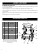


No. Part No. Description Qty.
1 73011-01 Seat Cushion 1
2 73011-02 Support Frame 2
3 73011-03 Washer - 6 4
4 73011-04 Screw M6 x 40 4
5 73011-05 Nut M8 4
6 73011-06 Washer - 8 4
7 73011-07 Nut M8 4
8 73011-08 Washer - 10 4
9 73011-09 Base Frame 1
10 73011-10 2-1/2 in. Caster 4
11 73011-11 Bolt M8 x 60 4
12 73011-12 Tray 1
13 73011-13 Reinforcement Bar 2
ASSEMBLY & ADJUSTMENTS
ASSEMBLING THE ROLLING SEAT
1. Use the four larger M8x60 bolts (11), washers (6), and M8 nuts (5) to connect the two support frames (2) to the
tray (12) and the base frame (9).
2. Place reinforcement bars (13) across the support frames, aligning the holes to allow for screws.
3. Use the four M6x40 screws (4) and washers (3) to attach the seat cushion (1) to the aligned support frames and
reinforcement bars.
4. Attach the four casters (10) along the underside of the unit and secure them using flat washers (8) and M8 nuts
(7).
5. Properly tighten all screws and nuts prior to operation.
EXPLODED VIEW & PARTS LIST
NOTE: Not all parts may be available for pur-
chase. Parts and accessories that wear down
over the course of normal use are not covered
under the warranty.
6