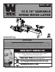
MODEL 34027 12 X 16" VARIABLE SPEED WOOD LATHE For replacement parts visit WENPRODUCTS.COM 4005911 IMPORTANT: Your new tool has been engineered and manufactured to WEN’s highest standards for dependability, ease of operation, and operator safety. When properly cared for, this product will supply you years of rugged, trouble-free performance. Pay close attention to the rules for safe operation, warnings, and cautions.
TABLE OF CONTENTS Specifications................................................................................... 2 Introduction..................................................................................... 3 General Safety Rules........................................................................ 4 Specific Safety Rules for the Wood Lathe......................................... 6 Electrical Information.......................................................................
INTRODUCTION Thanks for purchasing the WEN Wood Lathe. We know you are excited to put your tool to work, but first, please take a moment to read through the manual. Safe operation of this tool requires that you read and understand this operator’s manual and all the labels affixed to the tool. This manual provides information regarding potential safety concerns, as well as helpful assembly and operating instructions for your tool. SAFETY ALERT SYMBOL: Indicates danger, warning, or caution.
GENERAL SAFETY RULES Safety is a combination of common sense, staying alert and knowing how your item works. SAVE THESE SAFETY INSTRUCTIONS. WARNING: Read and understand all warnings, cautions and operating instructions before using this tool. Failure to follow all instructions listed below may result in personal injury and tool damage. WORK AREA SAFETY 1. Keep work area clean and well lit. Cluttered or dark areas invite accidents. 2.
GENERAL SAFETY RULES 4. Prevent unintentional starting. Ensure the switch is in the off-position before connecting to power source and/or battery pack, picking up or carrying the tool. Carrying power tools with your finger on the switch or energizing power tools that have the switch on invites accidents. 5. Remove any adjusting key or wrench before turning the power tool on. A wrench or a key left attached to a rotating part of the power tool may result in personal injury. 6. Do not overreach.
SPECIFIC RULES FOR THE WOOD LATHE WARNING: Do not let comfort or familiarity with the product replace strict adherence to product safety rules. Failure to follow the safety instructions may result in serious personal injury. 1. TOOL PURPOSE. This lathe is designed for turning wood or wood-like products only. Turning other materials could result in fire, injury, or damage to the workpiece.
SPECIFIC RULES FOR THE WOOD LATHE 12. PREVENTING ACCIDENTAL STARTING. Make sure the power switch is in the OFF position prior to plugging in the machine. Always make sure the power switch is in the OFF position and the machine is unplugged when doing any cleaning, assembly, setup operations, or when not in use. 13. Do not operate this tool until it is completely assembled and installed according to the instructions. 14.
ELECTRICAL INFORMATION GROUNDING INSTRUCTIONS IN THE EVENT OF A MALFUNCTION OR BREAKDOWN, grounding provides the path of least resistance for an electric current and reduces the risk of electric shock. This tool is equipped with an electric cord that has an equipment grounding conductor and a grounding plug. The plug MUST be plugged into a matching outlet that is properly installed and grounded in accordance with ALL local codes and ordinances. DO NOT MODIFY THE PLUG PROVIDED.
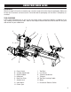
KNOW YOUR WOOD LATHE UNPACKING With the help of a friend or trustworthy foe, carefully remove the lathe from the packaging. Make sure to take out all contents and accessories. Do not discard the packaging until the lathe is completely assembled. TOOL PURPOSE Lathes rotate workpieces on an axis so you can create various symmetrical profiles in wood by chiseling, sanding, and using other tools. Refer to the diagram below to become familiarized with the parts and controls of your wood lathe.
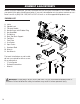
ASSEMBLY & ADJUSTMENTS Before using the wood lathe, you must assemble the unit using the instructions in this section. Check your packing list against the diagram below. If any part is damaged or missing, please contact our customer service at (800) 232-1195, M-F 8-5 CST or email us at techsupport@wenproducts.com. PACKING LIST A. B. C. D. E. F. G. H. I. J. K. L. M. N.
ASSEMBLY & ADJUSTMENTS INSTALLING SPINDLE LOCK Remove the spindle lock (Fig. 1 - 1) from the carton and install it onto the headstock with a wrench. WARNING: Disengage spindle lock before turning the machine on. The lock should be in its highest available position to prevent it from interfering with the rotation of the spindle (Fig. 5). INSTALLING HANDLE Attach the handle screw (Fig. 2 - 2) through the handle (Fig. 2 - 1) hole onto the handwheel. Secure it using a screwdriver.
ASSEMBLY & ADJUSTMENTS REMOVING THE FACE PLATE 1. Make sure the two set screws (Fig. 4 - 1 on p. 11) in the face plate (Fig. 4 - 2 on p. 11) have been backed out so they do not enter the central bore. Adjust them, if necessary, with the included hex wrench. 12 2. Engage the spindle lock (Fig. 5 on p. 11). 3. Use the provided wrench to unscrew the face plate (Fig. 6). Fig. 6 INSTALLING THE SPUR CENTER 1. Make sure the surfaces of both the spur center and the spindle are clean.
ASSEMBLY & ADJUSTMENTS INSTALLING TOOL REST When a workpiece is larger than the swing capacity on the bed, it can be turned by using the back face plate (Fig. 11 - 1) and tool rest (Fig. 11 - 6). To mount the tool rest to the back of the lathe: 1. Fit the back tool rest support (Fig. 11 - 3) to the rear of the lathe using three hex bolts and three flat washers (Fig. 11 - 2). 1 2 4 5 2. Remove the clamp (Fig. 11 - 4) and hex nut (Fig. 11 - 5) of tool rest base from the underside of the lathe. 6 3 3.
ASSEMBLY & ADJUSTMENTS TOOL REST ADJUSTMENTS Users can adjust the height, position and angle of the tool rest assembly. Loosen the locking lever (Fig. 14 - 1) on the tool rest base to slide the base forward and back or to adjust the angle of it. Tighten the locking lever firmly before operating the lathe. Loosen the small locking handle (Fig. 14 - 2) to raise and lower the tool rest or to adjust its angle. Tighten the handle before operating the lathe.
OPERATION OPERATING CONTROLS (FIG. 18) 1. Digital speed display - shows the current speed (RPM) of the spindle. 2. Protection Indicator - if the machine turns off and the protection indicator light begins to blink, it means that the motor was protected from overload. The workpiece may be too big or heavy for the current speed of the lathe. To reset it: - Turn off the main switch. - Wait two seconds and then turn it back on. - Work carefully and reduce the depth of the cut.
OPERATION TURNING TOOLS If possible, select only quality high-speed steel turning tools. High-speed steel tools hold an edge and last longer than ordinary carbon steel. As one becomes proficient in turning, a variety of specialty tools for specific applications can be acquired. The following tools provide the basics for most wood-turning projects. 1. Large roughing gouge - use this tool to shape square or out-of-round spindle-turning stock into a cylinder. This can also be used for creating shallow coves.
OPERATION SPINDLE TURNING Spindle turning takes place between the centers of the lathe. It requires a spur center in the headstock and a live center in the tailstock. A cup center rather than a cone center in the tailstock will often reduce the risk of splitting the stock. Stock for spindles should be straight grained and free of cracks, knots, nails and other defects. With a combination square, locate and mark the center on each end of the workpiece.
OPERATION CUTTING TECHNIQUES Begin with a large roughing gouge. Place the tool on the tool rest with the heel of the tool on the surface to be cut. Slowly and gently raise the tool handle until the cutting edge comes into contact with the workpiece. Beginning about 2 inches from the tailstock end of the workpiece, roll the flute of the tool (the hollowed-out portion) in the direction of the cut. Make long sweeping cuts in a continuous motion to turn the piece to a cylinder (Fig. 22). Fig.
OPERATION SANDING - Leaving clean cuts will reduce the amount of sanding required. Move the tool rest out of the way, adjusting the lathe to a low speed. Being with find sandpaper (120 grit or finer), as coarser sandpaper will leave deep scratches and dull the features of the workpiece. Progress through each grit without skipping grits (as in, don’t jump from 120 grit to 220 grit). Fold the sandpaper into a pad; do not wrap sandpaper around your fingers or the workpiece.
OPERATION TO SHAPE THE OUTSIDE OF THE BOWL (FIG. 26) Odd shaped burls, crotches and other irregular shaped blanks require special preparation before mounting in a chuck or onto a face plate. Remove the bark, if there is any from what appears to be the center of the top of the workpiece. Drive the spur center into the top of the workpiece with a mallet or a dead blow hammer. Slip the spur center into the headstock taper and bring the tailstock with a live center into position.
OPERATION piece. Should there be a few small ridges left, a light cut with a large domed scraper can even out the surface. Develop the preferred wall thickness at the rim and maintain it as you work deeper into the bowl (once the piece is thin toward the bottom, you cannot make it thinner at the rim). When the interior is finished, move the tool rest back to the exterior to re-define the bottom of the bowl. Work the tight area around the face plate or the chuck with a bowl gouge.
TROUBLESHOOTING GUIDE WARNING: Stop using the tool immediately if any of the following problems occur. Repairs and replacements should only be performed by an authorized technician. For any questions, please contact our customer service at (800) 232-1195, M-F 8-5 CST or email us at techsupport@ wenproducts.com. PROBLEM Motor or spindle stalls and will not start CAUSE SOLUTION Excessive cut Reduce the depth of the cut Worn, damaged, or improperly adjusted belt Adjust or replace the belt.
EXPLODED VIEW & PARTS LIST 23
EXPLODED VIEW & PARTS LIST 24 No. Part No. Description Qty. No. Part No. Description Qty.
EXPLODED VIEW & PARTS LIST No. Part No. Description Qty. No. Part No. Description Qty.
WARRANTY STATEMENT WEN Products is committed to building tools that are dependable for years. Our warranties are consistent with this commitment and our dedication to quality. LIMITED WARRANTY OF WEN CONSUMER POWER TOOLS PRODUCTS FOR HOME USE GREAT LAKES TECHNOLOGIES, LLC (“Seller”) warrants to the original purchaser only, that all WEN consumer power tools will be free from defects in material or workmanship for a period of two (2) years from date of purchase.