4" x 20" VARIABLE SPEED WOOD LATHE Model # 34034 For replacement parts visit WENPRODUCTS.COM bit.ly/wenvideo IMPORTANT: Your new tool has been engineered and manufactured to WEN’s highest standards for dependability, ease of operation, and operator safety. When properly cared for, this product will supply you years of rugged, trouble-free performance. Pay close attention to the rules for safe operation, warnings, and cautions.
TABLE OF CONTENTS Product Specifications Safety Introduction General Safety Rules Specific Rules for Wood Lathes Electrical Information Know Your Wood Lathe Assembly & Adjustments Operation Maintenance Exploded View & Parts List Troubleshooting Warranty Statement 2 3 4 6 7 8 9 13 19 20 22 23 PRODUCT SPECIFICATIONS Model Number: Motor: Swing Over Bed: Distance Between Centers: Center Height: Spindle Speeds: Spindle Taper: Spindle Thread: Tailstock Taper: Quill Travel: Tool Rest Length: Face Plate Diameter:
SAFETY INTRODUCTION Thanks for purchasing the WEN Lathe. We know you are excited to put your tool to work, but first, please take a moment to read through the manual. This manual provides information regarding potential safety concerns, as well as helpful assembly and operating instructions. Safe operation of this tool requires that you read and understand this operator’s manual and all labels affixed to the tool. SAFETY ALERT SYMBOL: Indicates danger, warning, or caution.
GENERAL SAFETY RULES WARNING! Read all safety warnings and instructions. Failure to follow all instructions may result in electric shock, fire and serious injury. The term “power tool” in the warnings refers to your mainsoperated (corded) power tool. Save all warnings and instructions for future reference. WORK AREA SAFETY 1. Keep work area clean and well lit. Cluttered or dark areas invite accidents. 2.
GENERAL SAFETY RULES 6. Dress properly. Do not wear loose clothing or jewelry. Keep your hair, clothing and gloves away from moving parts. Loose clothes, jewelry or long hair can be caught in moving parts. 7. If devices are provided for the connection of dust extraction and collection facilities, ensure these are connected and properly used. Use of dust collection can reduce dust-related hazards. POWER TOOL USE AND CARE 1. Do not force the power tool. Use the correct power tool for your application.
SPECIFIC RULES FOR WOOD LATHES 1. This lathe is designed and intended for use by properly trained and experienced personnel only. If you are not familiar with the proper and safe operation of a lathe, do not use it until proper training and knowledge have been acquired. 2. Always wear ANSI Z87.1-approved eye protection and a face shield/dust mask when using the lathe. 3. DO NOT wear loose clothing or jewelry. Keep your hair, clothing and gloves away from moving parts.
ELECTRICAL INFORMATION GROUNDING INSTRUCTIONS In the event of a malfunction or breakdown, grounding provides the path of least resistance for an electric current and reduces the risk of electric shock. This tool is equipped with an electric cord that has an equipment grounding conductor and a grounding plug. The plug MUST be plugged into a matching outlet that is properly installed and grounded in accordance with ALL local codes and ordinances (Fig. A). DO NOT MODIFY THE PLUG PROVIDED.
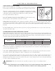
KNOW YOUR WOOD LATHE Carefully remove the tool and all contents from the packaging. Check all components and compare against the diagram below. If any part is damaged or missing, please contact our customer service at (800) 232-1195, M-F 8-5 CST or email us at techsupport@wenproducts.com. 6 2 1 20 3 7 5 4 19 8 18 9 17 13 14 16 11 10 15 1. Belt Drive Access Panel Knob 2. Face Plate 3. Tool Rest 4. Tool Rest Locking Handle 5. Quill Locking Handle 6. Tailstock 7. Tailstock Handle 8.
ASSEMBLY & ADJUSTMENTS WARNING: To prevent injury from accidental operation, make sure the tool is switched OFF and unplugged from the power source before assembling or making any adjustments. CLEANING THE MACHINE Your tool comes protected with a layer of anti-rust coating. Wipe off the coating using an acetone-moistened cloth. DO NOT use cellulose-based solvents such as paint thinner or lacquer thinner, as these will damage the painted surfaces.
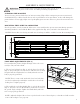
ASSEMBLY & ADJUSTMENTS F SETTING UP THE FACE PLATE (Fig. 3 & 4) NOTE: When installing the face plate for turning bowls and plates, mount the workpiece onto the face plate prior to installing the face plate on the headstock (see page 18). To install the face plate: 1. Thread the face plate (Fig. 3 - 1) onto the headstock spindle E by turning it clockwise as far as it will go, and then tighten the two set screws with a hex wrench (Fig. 3 - 2). 2. Lock the spindle lock (Fig.
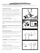
ASSEMBLY & ADJUSTMENTS TAILSTOCK ADJUSTMENTS (Fig. 7) Loosen the tailstock locking lever (Fig. 7 - 1) and slide the tailstock along the lathe bed into the desired position. Retighten the locking lever. 3 2 Loosen the quill locking handle (Fig. 7 - 2) just enough to unlock the tailstock quill. Turn the handwheel (Fig. 7 - 3) clockwise to advance the quill and counterclockwise to retract the quill. Retighten the quill locking handle. SETTING UP THE TAILSTOCK LIVE CENTER (Fig.
8 7 6 ASSEMBLY & ADJUSTMENTS F ADJUSTING THE SPEED (Fig. 11 - 14) Your variable speed lathe has three speed ranges: Low 250-720 RPM, Medium 600-1700 RPM, and High 1200-3550 RPM. AlD ways start at slower speeds for rough cuts and larger workpieces. Use faster speeds for refined cuts and detailed work. D Set the suitable speed range for your operation by adjusting the belt position. Change the speed within a speed range using the speed adjustment knob.
OPERATION TURNING TOOLS If possible, select only quality high-speed steel turning tools. High-speed steel tools hold an edge and last longer than ordinary carbon steel. As one becomes proficient in turning, a variety of specialty tools for specific applications can be acquired. The following tools provide the basics for most woodturning projects. 1. Roughing gouge - use this tool to shape square or out-of-round spindle-turning stock into a cylinder. This can also be used for creating shallow coves. 2.
OPERATION - SPINDLE TURNING WARNING: To prevent serious injury, make sure all the warnings and instructions have been read and understood before operating this tool. MOUNTING THE WORKPIECE BETWEEN SPINDLES (Fig. 16 & 17) Spindle turning takes place between the centers of the lathe, with the workpiece being held between the spur center in the headstock and the live center in the tailstock. The wood stock for spindle turning should be straight grained and free of cracks, knots, nails and other defects.
OPERATION - SPINDLE TURNING The following operation instructions serves as a beginning point for some common lathe operations. Practice on scrap material to become familiarized with the operation process and make the necessary adjustments before working on your workpiece. ROUGHING OUT CUT Roughing out is the first step of the lathe operation, which uses the large roughing gouge tool to smooth out sharp corners to make the workpiece cylindrical.
OPERATION - SPINDLE TURNING CREATING BEADS Making a parting cut for the desired depth and location of your bead. 1. Place the parting tool on the tool rest and move the tool forward to make the full bevel of the tool come into contact with the workpiece. Gently raise the handle to make cuts of the appropriate depth. Repeat for the other side of the bead. 2. Using a small skew or spindle gouge, start in the center between the two cuts and cut down each side to form the bead.
OPERATION - SPINDLE TURNING SANDING THE WORKPIECE Adjust the lathe to a slower speed for sanding and finishing. High speed can build friction while sanding and cause burns in some woods. The cleaner the cuts, the less sanding will be required. So try to make the cuts as refined as you can before moving to the sanding process. 1. Use sandpaper finer than 120 grit, as coarse sandpaper may scratch the workpiece. Fold the sandpaper into a pad will allow easier and safer sanding.
OPERATION - BOWL TURNING MOUNTING THE WORKPIECE ONTO THE FACE PLATE When turning bowls or plates with a large diameter, mounting it to the face plate to gives the maximum amount of support. While face plates are the most reliable method for holding a larger block of wood for turning, a lathe chucks can also be used. A chuck is handy when working on more than one piece at a time, allowing your to open the chuck and change workpieces instead of having to remove the mounting screws. 1.
MAINTENANCE WARNING: Disconnect the machine from the power source before making any maintenance or adjustments. Failure to do so may result in serious injury. GENERAL MAINTENANCE 1. Keep your machine clean. Wood contains moisture, meaning that sawdust and wood chips can cause rust if not removed. At the end of each work day, vacuum sawdust and clean the machine with a dry cloth or brush. 2. Periodically check that all nuts and bolts are tight. 3.
EXPLODED VIEW & PARTS LIST 20
EXPLODED VIEW & PARTS LIST No. 1 Part No.
TROUBLESHOOTING WARNING: Stop using the tool immediately if any of the following problems occur. Repairs and replacements should only be performed by authorized personnel. If you have any questions, please contact our customer service at (800) 232-1195, M-F 8-5 CST or email us at techsupport@wenproducts.com. PROBLEM CAUSE Power cord damaged or not properly plugged in. Defective power switch. Motor will not start SOLUTION Check the power cord, extension cord, power plug and the power outlet.
LIMITED TWO YEAR WARRANTY WEN Products is committed to build tools that are dependable for years. Our warranties are consistent with this commitment and our dedication to quality. LIMITED WARRANTY OF WEN CONSUMER POWER TOOLS PRODUCTS FOR HOME USE GREAT LAKES TECHNOLOGIES, LLC (“Seller”) warrants to the original purchaser only, that all WEN consumer power tools will be free from defects in material or workmanship for a period of two (2) years from date of purchase.
THANKS FOR REMEMBERING